
Active capacitive control stylus

a capacitive control and active technology, applied in the field of active capacitive control stylus, can solve the problems of current methods of transferring data through capacitive touch screen, input is limited to the speed,

Inactive Publication Date: 2014-02-11
THE UNITED STATES OF AMERICA AS REPRESENTED BY THE SECRETARY OF THE NAVY
View PDF23 Cites 75 Cited by
  • Summary
  • Abstract
  • Description
  • Claims
  • Application Information

AI Technical Summary

Benefits of technology

This patent describes a device and method for transferring data to a capacitive touch screen. The device includes a body, a tip with a special dielectric constant value, a control unit, and an electronic switch. The tip is designed to interact with the touch screen and the switch is connected to the control unit. The switch can be opened or closed to connect or disconnect the tip to a ground source. When the tip comes into contact with the touch screen, the switch is quickly opened and closed to transfer serial data into the screen. This technology allows for quick and efficient data transfer to capacitive touch screens.

Problems solved by technology

Such input is limited to the speeds at which a human can reasonably input via screen touches.
However, current methods of transferring data through a capacitive touch screen are limited by their reliance on visual feedback and sequential input.

Method used


Image

  • Active capacitive control stylus
  • Active capacitive control stylus
  • Active capacitive control stylus

Examples


Embodiment Construction

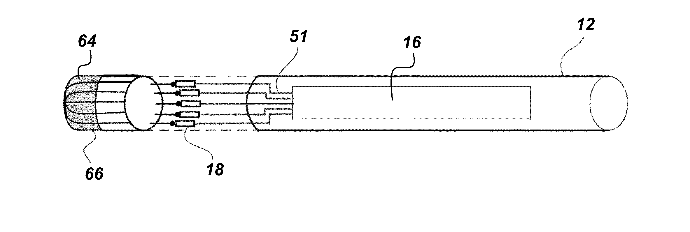
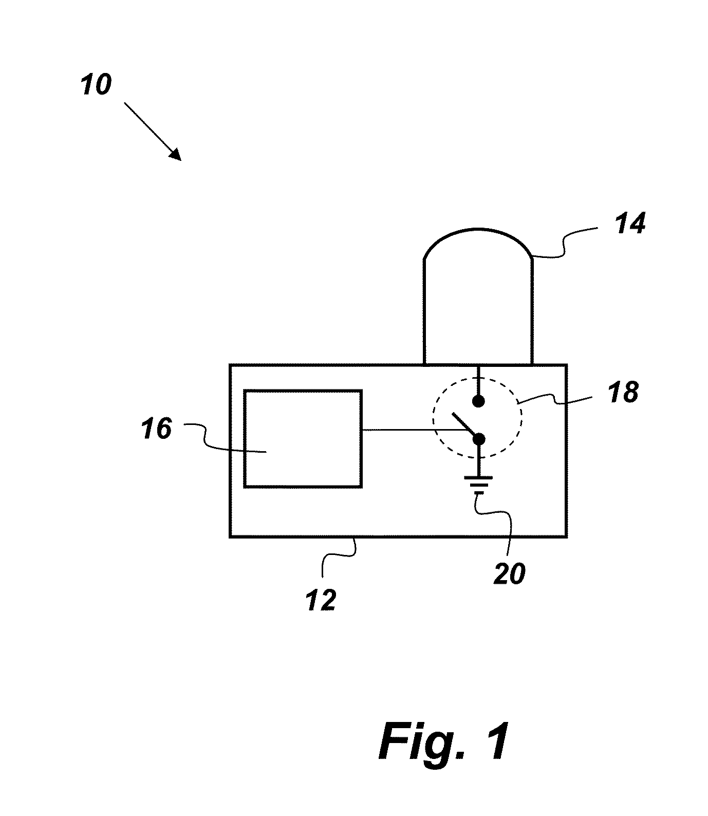
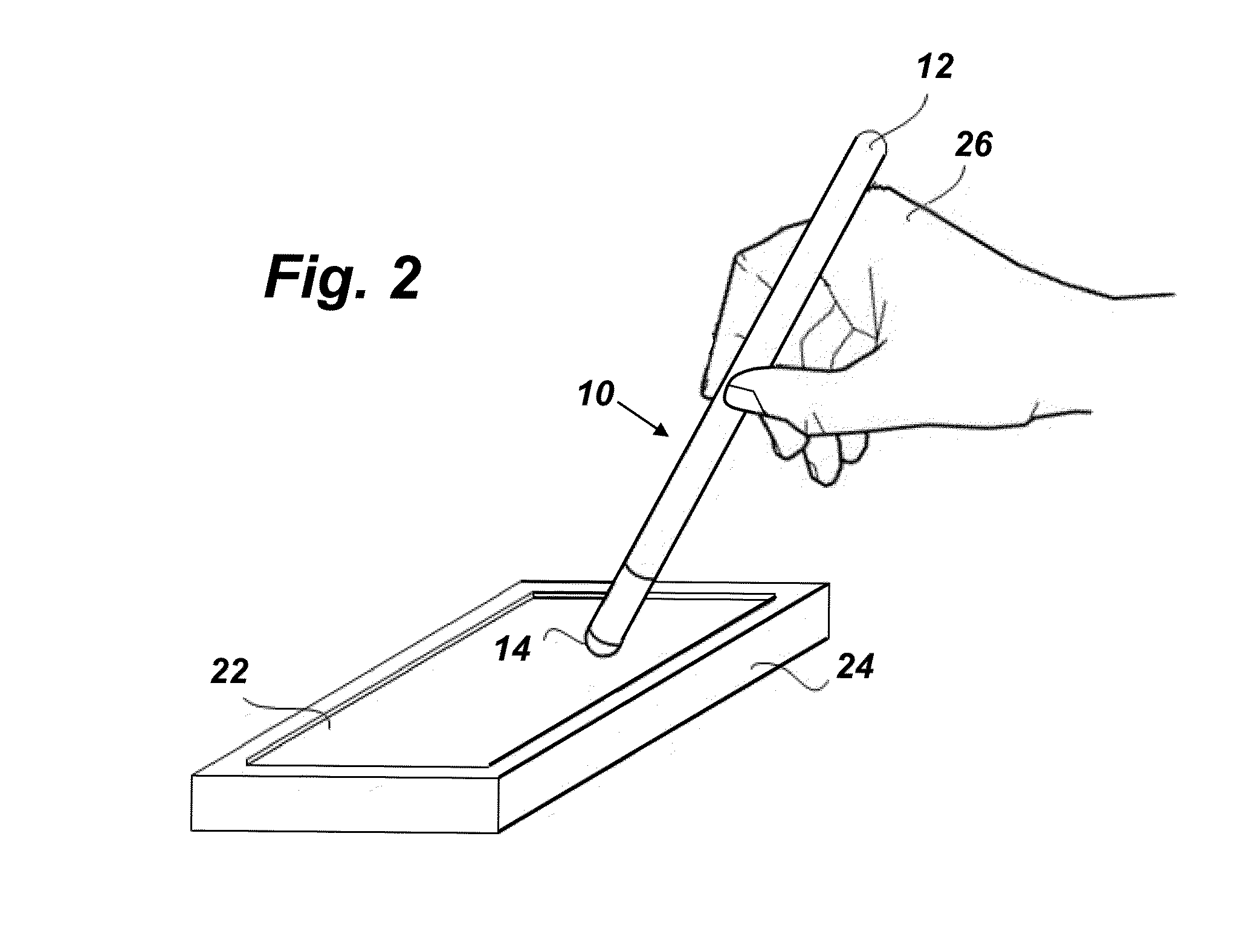
[0023]FIG. 1 is an illustration of a data transfer device 10. As shown in FIG. 1, the data transfer device 10 comprises a body 12, a tip 14, a control unit 16, and an electronic switch 18. The tip 14, which is coupled to the body 12, has a dielectric constant value that is suitable for interacting with a capacitive touch screen of a separate device such as the one shown in FIGS. 2a-2b. The control unit 16 and the electronic switch 18 are both mounted to the body 12. The switch 18 is operatively coupled to the control unit 16 such that the control unit 16 controls the opening and closing of the switch 18. The switch 18 is disposed to connect the tip 14 to a ground source 20 when the switch 18 is in a closed configuration and to break the connection between the tip 14 and the ground source 20 when the switch 18 is in an open configuration. In other words, the tip 14 is electrically isolated from the ground source 20, but for the switch 18. The data transfer device 10 may be used to tr...


PUM


Abstract

A data transfer device comprising: a body; a tip coupled to the body, wherein the tip has a dielectric constant value suitable for interacting with a capacitive touch screen of a separate device; a control unit mounted to the body; and an electronic switch mounted to the body and operatively coupled to the control unit, wherein the switch is disposed to connect the tip to a ground source when the switch is in a closed configuration and to break the connection between the tip and the ground source when the switch is in an open configuration.

Description

FEDERALLY-SPONSORED RESEARCH AND DEVELOPMENT[0001]This invention is assigned to the United States Government and is available for licensing for commercial purposes. Licensing and technical inquiries may be directed to the Office of Research and Technical Applications, Space and Naval Warfare Systems Center, Pacific, Code 72120, San Diego, Calif., 92152; voice (619) 553-2778; email T2@spawar.navy.mil. Reference Navy Case Number 100270.BACKGROUND OF THE INVENTION[0002]This invention relates generally to devices for transferring data through a capacitive touch screen. In recent years capacitive sensing technology has been integrated and employed in many electronic applications and devices. The capacitive sensor is replacing conventional mechanical switches and buttons used to input data and control operating machines, computer systems, games, and electronic portable devices. Touch screens on phones and other handheld devices are exemplary in their use of capacitive sensing technology. ...

Claims


Application Information

Patent Timeline
IPC IPC(8): G06F3/033
CPCG06F3/044G06F3/0416G06F3/03545G06F3/033G06F3/04162G06F3/0442
Inventor TRAN, NGHIA X.PHAN, HOA V.FUGATE, SUNNY J.BRUCH, MICHAEL H.
Owner THE UNITED STATES OF AMERICA AS REPRESENTED BY THE SECRETARY OF THE NAVY
Learn More