Electric telescopic steering apparatus

a technology of electric telescopic steering and steering column, which is applied in the direction of steering column, steering parts, vehicle components, etc., can solve the problems of insufficient absorption of deviation, reduced support rigidity, and inability to manipulate the feeling and visual quality

Inactive Publication Date: 2014-02-18
FUJI KIKO CO LTD
View PDF27 Cites 55 Cited by
  • Summary
  • Abstract
  • Description
  • Claims
  • Application Information

AI Technical Summary

Benefits of technology

[0006]On the other hand, it is conceivable that a structure in which the universal joint as used in the Patent Document 1 is provided to the screw shaft of the telescopic mechanism is employed in order to smoothly performing the telescopic adjustment by smoothly transmitting rotational force even if the screw shaft becomes nonparallel to the jacket.

Problems solved by technology

In such a case, manipulating feeling and visual quality are not favorable.
However, in this case, there are a problem that a support rigidity is reduced, and a problem that the deviation comes to be insufficiently absorbed when the deviation of shaft axis becomes somewhat large.
In this case, there are a problem that the number of components is increased, a problem that a freedom degree of layout is reduced, and a problem that an assembling performance is worsened.

Method used


Image

  • Electric telescopic steering apparatus
  • Electric telescopic steering apparatus
  • Electric telescopic steering apparatus

Examples


first embodiment

[0016][First Embodiment]

[0017]At first, a first embodiment according to the present invention will now be explained.

[0018](Structures)

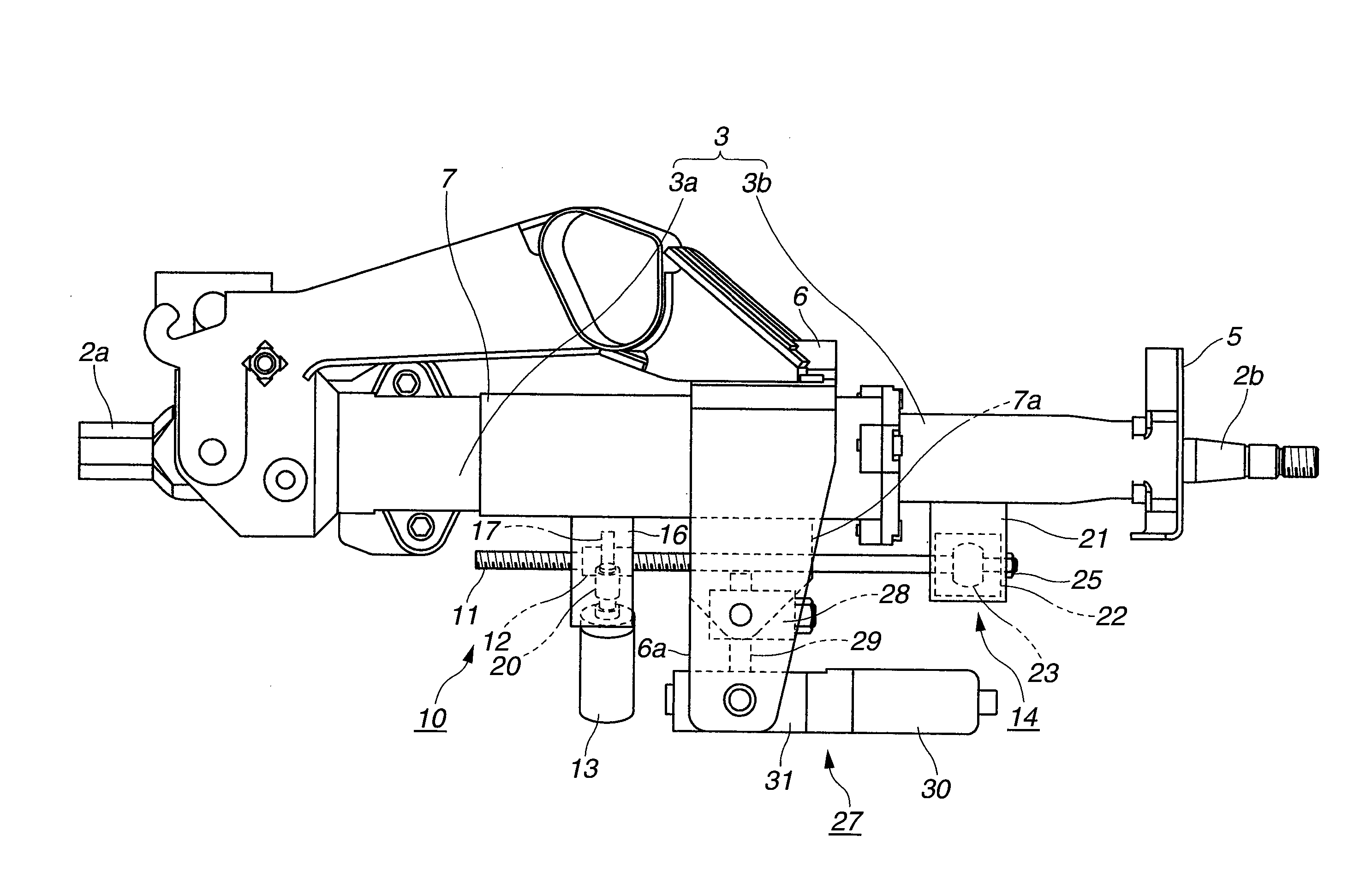
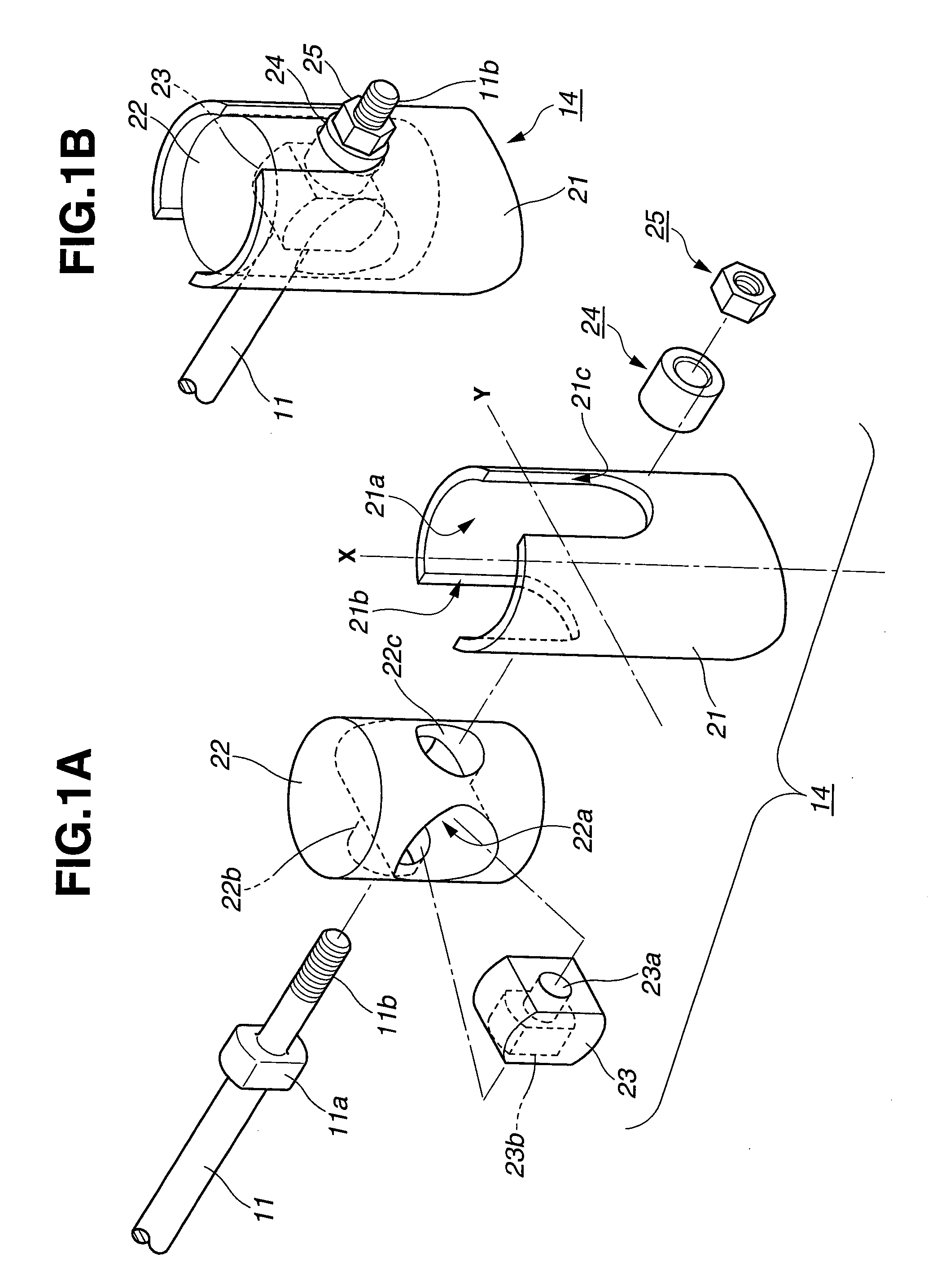
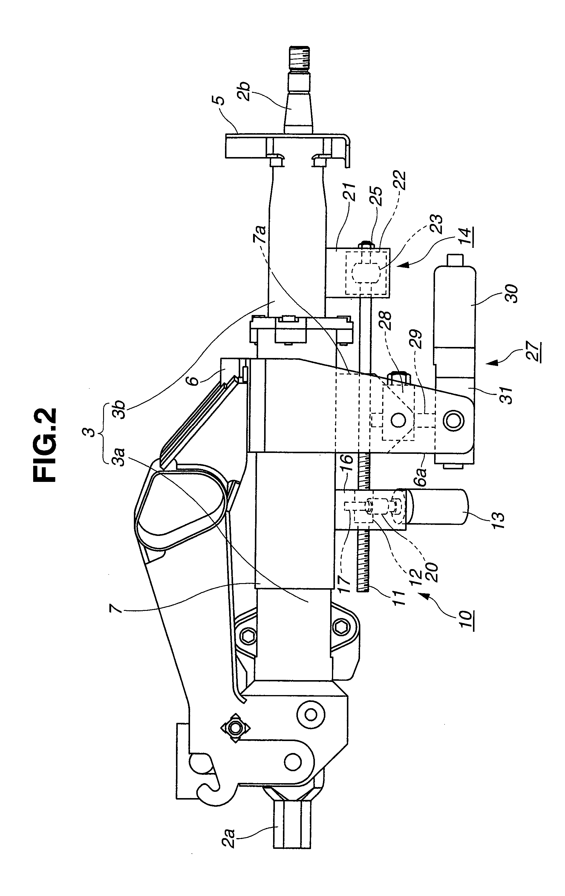
[0019]A steering apparatus 1 is constructed as shown in FIGS. 2 and 3. The steering apparatus 1 includes a jacket 3, and a shaft 2 having a lower shaft (shaft element) 2a and an upper shaft (shaft element) 2b. The lower shaft 2a is connected to a rack-and-pinion mechanism for operating a steerable road wheel(s) (not shown). The upper shaft 2b is able to slide on (slide in contact with) the lower shaft 2a, under a state where a relative rotation between the lower shaft 2a and the upper shaft 2b is restricted or locked by a spline-fitting portion 2c. Thereby, the shaft 2 is retractable, i.e., is capable of increasing and decreasing in length. That is, the shaft 2 can vary telescopically. A steering wheel (not shown) is provided on a tip portion of the upper shaft 2b. The jacket 3 includes a lower jacket (jacket element) 3a and an upper jacket (jacket el...

second embodiment

[0037][Second Embodiment]

[0038]Next, a second embodiment according to the present invention will now be explained. In the second embodiment, the displacement absorbing section 14 of the first embodiment is partly modified into a displacement absorbing section 14′ in order to make the assembling of the displacement absorbing section become easier. Explanations about structures same as those of the first embodiment will be omitted for a simplification of the disclosure. Only structures different from those of the first embodiment will now be explained.

[0039](Structures)

[0040]As shown in FIG. 4A, a screw shaft 11′ which corresponds to the screw shaft 11 of the first embodiment includes a retaining member 23′ at one end (steering-wheel-side end) of the screw shaft 11′. The retaining member 23′ is formed in a cylindrical-column shape. The retaining member 23′ is formed integrally with the screw shaft 11′. An intermediate member 22′ which corresponds to the intermediate member 22 of the f...


PUM


Abstract

An electric telescopic steering apparatus includes a jacket having a lower jacket and an upper jacket in order to telescope the jacket; and a screw shaft arranged along a longitudinal direction of the jacket and held under a rotation-locked state. The screw shaft includes one end portion supported by one of the lower jacket and the upper jacket. The electric telescopic steering apparatus further includes a nut screwed on another end portion of the screw shaft and supported by another of the lower jacket and the upper jacket; a driving section configured to drive a rotation of the nut; and a displacement absorbing section provided between the one end portion of the screw shaft and the jacket. The displacement absorbing section is configured to permit the one end portion of the screw shaft to be displaced on an X-Y plane defined by an imaginary X-axis and an imaginary Y-axis which are substantially perpendicular to an axis of the screw shaft, and configured to permit an angle of the axis of the screw shaft to vary about the X-axis and the Y-axis.

Description

BACKGROUND OF THE INVENTION[0001]The present invention relates to an electric telescopic steering apparatus adapted to absorb a deviation of a screw shaft which is used for a telescopic mechanism.[0002]An electric telescopic steering apparatus for operating a telescopic mechanism by an electric motor has been used for a vehicle. Generally, the electric telescopic steering apparatus is constructed as follows. A telescopic jacket includes one jacket (element) and another jacket (element). The another jacket is provided to be able to slide in contact with the one jacket in an axial direction thereof. One end of a screw shaft disposed substantially parallel to the telescopic jacket is supported by the one jacket, and a nut is screwed on another end of the screw shaft. This nut is supported by the another jacket. One of the screw shaft and the nut is connected with a driving means, and another of the screw shaft and the nut is held by the telescopic jacket under a rotation-locked state. ...

Claims


Application Information

Patent Timeline
Patent Type & Authority Patents(United States)
IPC IPC(8): B62D1/18
CPCB62D1/181
Inventor MATSUNO, MITSUYOSHIITO, TADAOMIYAGI, TAKESHI
Owner FUJI KIKO CO LTD
Why Eureka
Try Eureka