Fiber diagnosis system for point-to-point optical access networks

a fiber optic network and diagnosis system technology, applied in the field of fiber optic network diagnostic equipment, can solve the problems affecting the adoption rate of fttp communication services, detection and location of fiber, etc., and achieve the effect of efficient identification and location of fiber faults

Active Publication Date: 2014-02-18
GOOGLE LLC
View PDF29 Cites 52 Cited by
  • Summary
  • Abstract
  • Description
  • Claims
  • Application Information

AI Technical Summary

Benefits of technology

[0003]Implementations of techniques and systems are provided for a point-to-point (pt-2-pt) optical access network that includes a test signal distribution unit for multiplexing an optical test signal across many pt-2-pt fiber links to efficiently identify and locate fiber faults.

Problems solved by technology

However, ongoing operation and maintenance expenses associated with the fiber plant also impact the adoption rate of FTTP communication services.
One such expense is the detection and location of fiber faults (e.g., a fiber cut or breakage) that interrupt communication services.

Method used


Image

  • Fiber diagnosis system for point-to-point optical access networks
  • Fiber diagnosis system for point-to-point optical access networks
  • Fiber diagnosis system for point-to-point optical access networks

Examples


Embodiment Construction

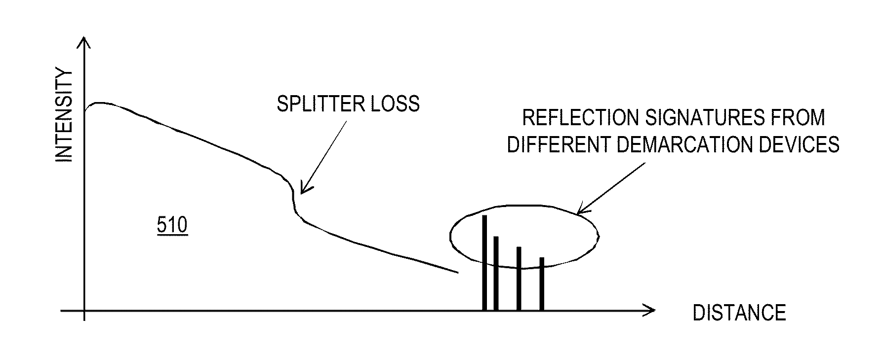
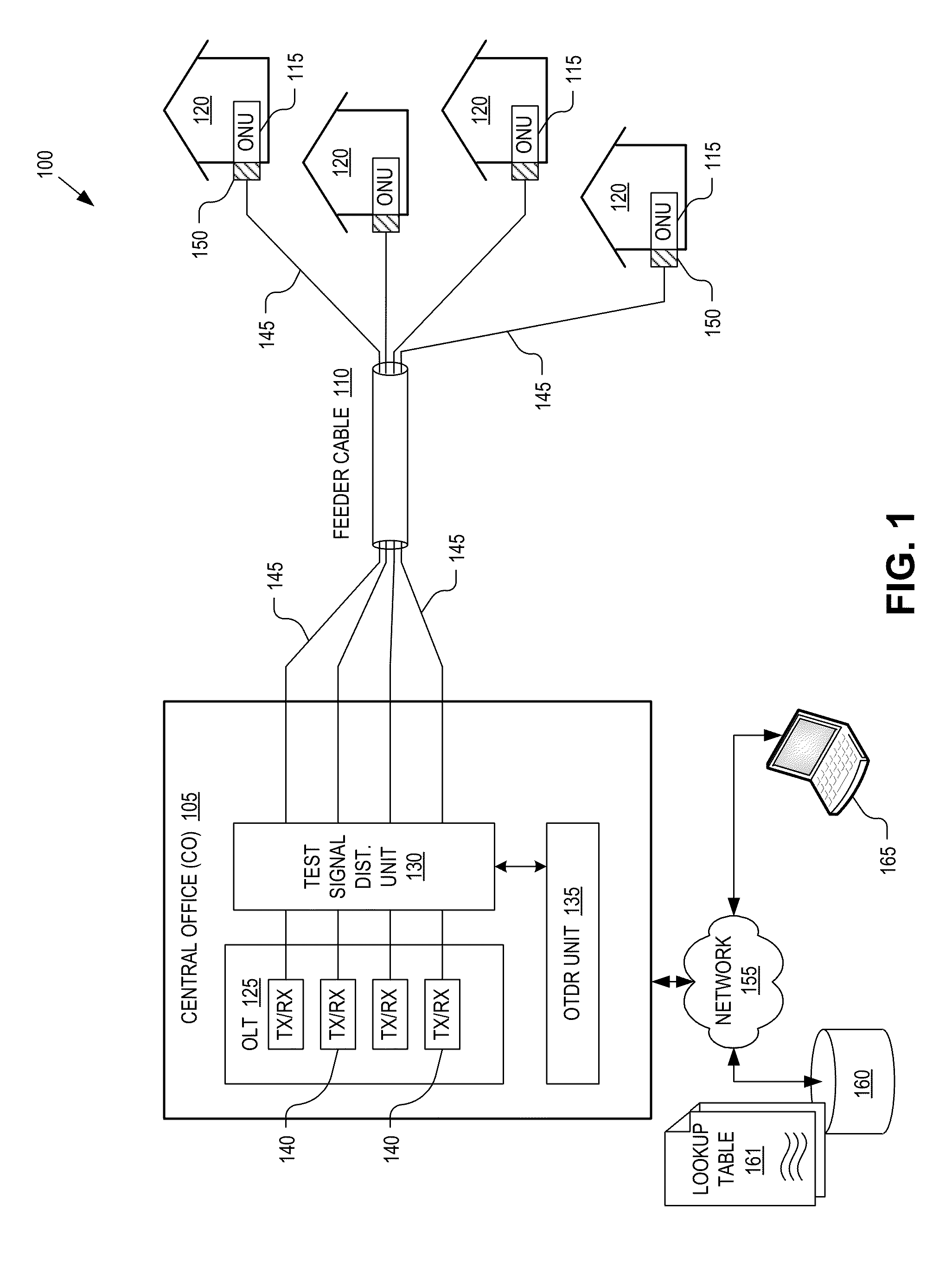
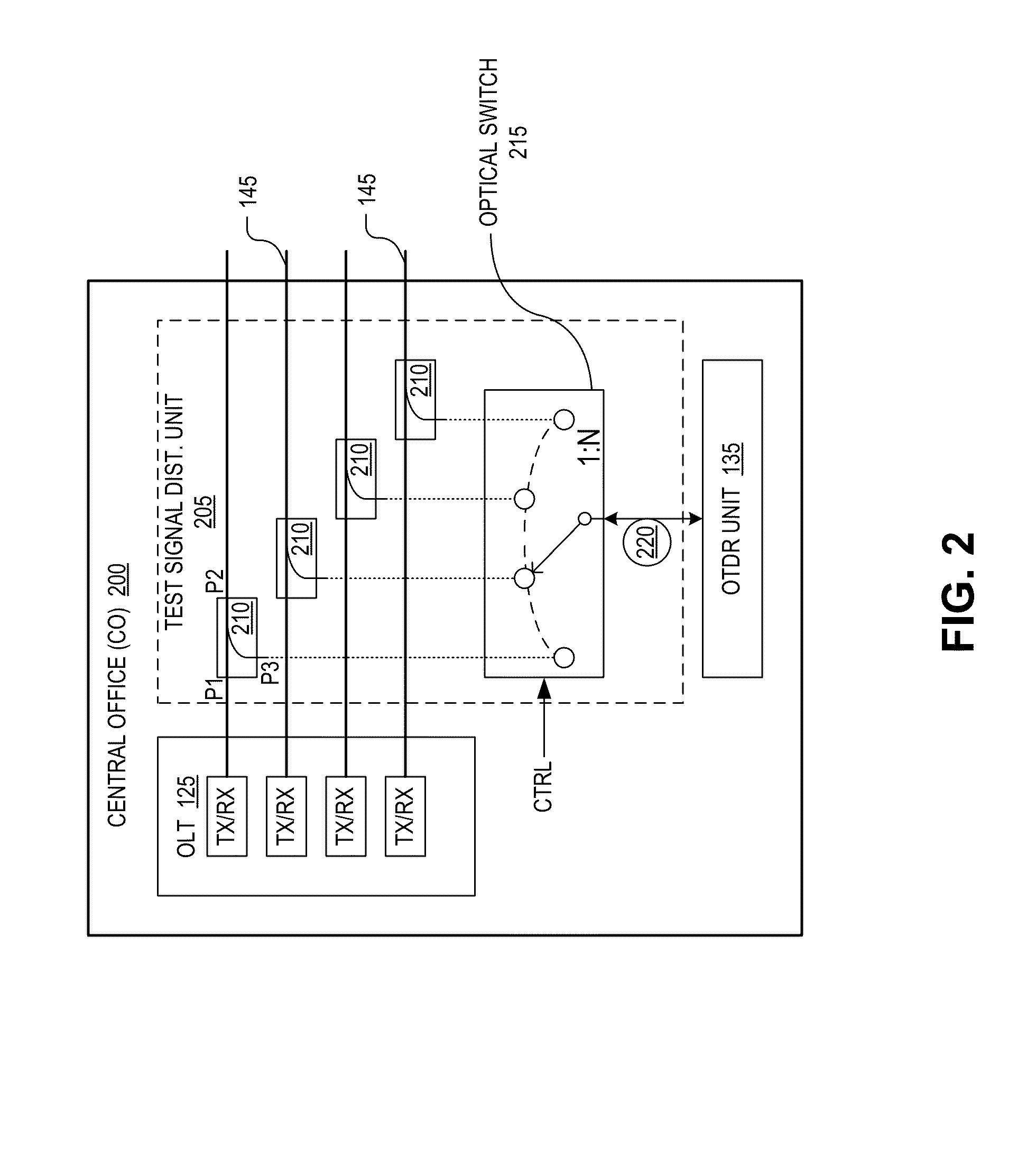
[0015]Embodiments of a system and method of operation of a point-to-point (pt-2-pt) fiber-to-the-premise (“FTTP”) access network that includes a test signal distribution unit for multiplexing an optical time domain reflectometry (“OTDR”) unit across many pt-2-pt fiber links to efficiently identify and locate fiber faults are described herein. In the following description numerous specific details are set forth to provide a thorough understanding of the embodiments. One skilled in the relevant art will recognize, however, that the techniques described herein can be practiced without one or more of the specific details, or with other methods, components, materials, etc. In other instances, well-known structures, materials, or operations are not shown or described in detail to avoid obscuring certain aspects.

[0016]Reference throughout this specification to “one embodiment” or “an embodiment” means that a particular feature, structure, or characteristic described in connection with the ...


PUM


Abstract

Implementations of techniques and systems are disclosed for detecting a fiber fault in a point-to-point optical access network based on optical time domain reflectometry (“OTDR”) measurements. The techniques include identifying loss of service between a central office (“CO”) and a given optical network unit (“ONU”) of a plurality of ONUs. In response to the identifying the loss of service, configuring a test signal distribution unit to optically couple an OTDR unit to a selected subset of the point-to-point fiber links which includes the given ONU. An optical test signal is launched from the OTDR unit into the selected subset of the point-to-point fiber links via the test signal distribution unit. Test signal reflections are received from each of the point-to-point fiber links within the selected subset as a reflection signature, which is analyzed to identify a location of the fiber fault.

Description

TECHNICAL FIELD[0001]This disclosure relates generally to fiber optic networks, and in particular but not exclusively, relates to diagnostic equipment for fiber optic networks.BACKGROUND INFORMATION[0002]Fiber networks can be used to transport light that is modulated to carry information and to deliver communication services in various configurations, including broadband fiber-to-the-premise (“FTTP”) communication services. In order to promote widespread deployment of FTTP broadband infrastructure, it is desirable to reduce the cost of fiber plant construction, which consists of as much as 80% of the total cost for FTTP deployments and is dominated by labor costs in developed countries. Techniques that can reduce this upfront expense associated with the initial fiber plant can further this goal. However, ongoing operation and maintenance expenses associated with the fiber plant also impact the adoption rate of FTTP communication services. One such expense is the detection and locati...

Claims


Application Information

Patent Timeline
Patent Type & Authority Patents(United States)
IPC IPC(8): H04B10/00
CPCH04B10/00H04B10/071H04Q2011/0083H04Q11/0067G01M11/3109H04J14/0212H04J14/0227
Inventor LAM, CEDRIC F.KELLY, JAMES F.SCHUH, AUSTIN B.
Owner GOOGLE LLC
Why Eureka
Try Eureka