
Electrophotographic printer with compressible-backup transfer station

a transfer station and electrotrophotographic printer technology, applied in the field of printing, can solve problems such as image artifacts in other modules, and achieve the effects of dampening shock waves, reducing the magnitude of shock waves, and reducing the occurrence or severity of image artifacts

Inactive Publication Date: 2014-02-18
EASTMAN KODAK CO
View PDF12 Cites 1 Cited by
  • Summary
  • Abstract
  • Description
  • Claims
  • Application Information

AI Technical Summary

Benefits of technology

[0010]Various schemes have been proposed to solve this problem. For example, the nip can be actively opened before the sheet reaches it and then closed to engage the sheet. However, this scheme increases the difficulty of producing borderless prints, since the top of the sheet is not firmly engaged in the nip as the nip closes. Moreover, this scheme cannot be used in friction-drive systems in which the transport web provides the motive power for the other rotating components of the printer. There is a continuing need, therefore, for a way of reducing the power of shock waves that can cause image artifacts.
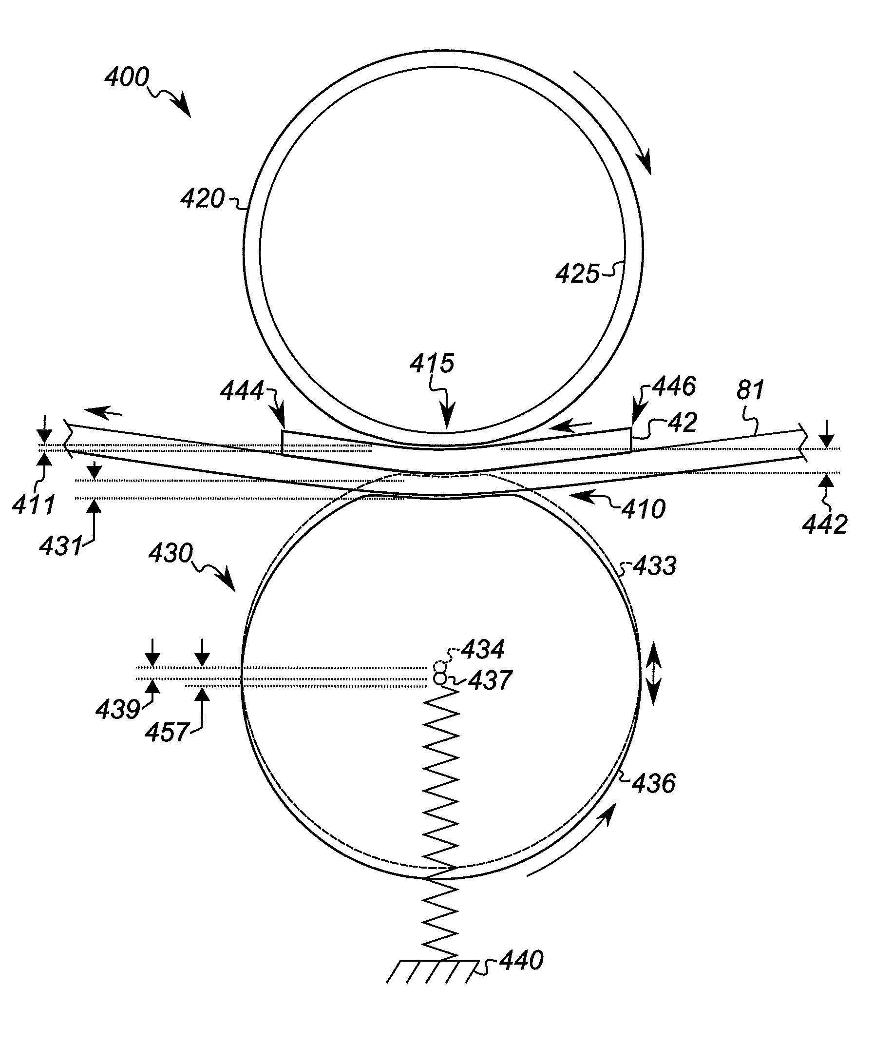
[0018]An advantage of this invention is that it reduces the magnitude of shock waves created when the lead edge or trail edge of a receiver enters or exits the transfer nip, thereby reducing the occurrence or severity of image artifacts. Another advantage is that it can dampen shock waves created when the lead edge or trail edge of a receiver enters or exits a transfer nip upstream or downstream of a selected transfer nip, thereby reducing image artifacts in the selected transfer nip. Yet another advantage is that it reduces the sensitivity of the printer image quality to receiver thickness, image-bearing member compliance, transport web tension, and transfer nip load pressure. Various embodiments reduce artifacts due to shock waves in non-friction-driven systems or in friction-driven systems. Various embodiments reduce artifacts even when the nip-forming member is opposite the receiver with respect to a transport web including a very stiff layer.

Problems solved by technology

However, when multiple print modules are printing on one or more receiver sheets simultaneously, mechanical disturbances from one printing module can produce image artifacts in other modules. FIGS. 3A-3D show an example of this problem as it occurs in one printing module.

Method used


Image

  • Electrophotographic printer with compressible-backup transfer station
  • Electrophotographic printer with compressible-backup transfer station
  • Electrophotographic printer with compressible-backup transfer station

Examples


Embodiment Construction

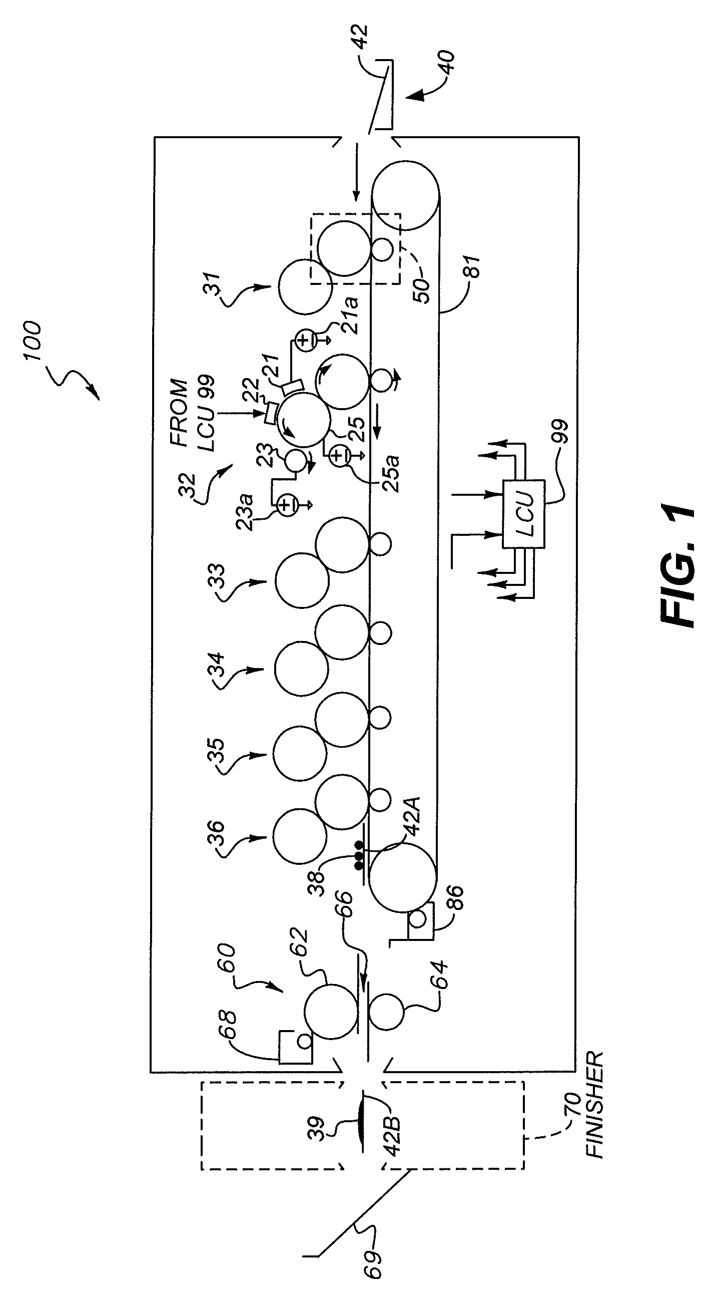
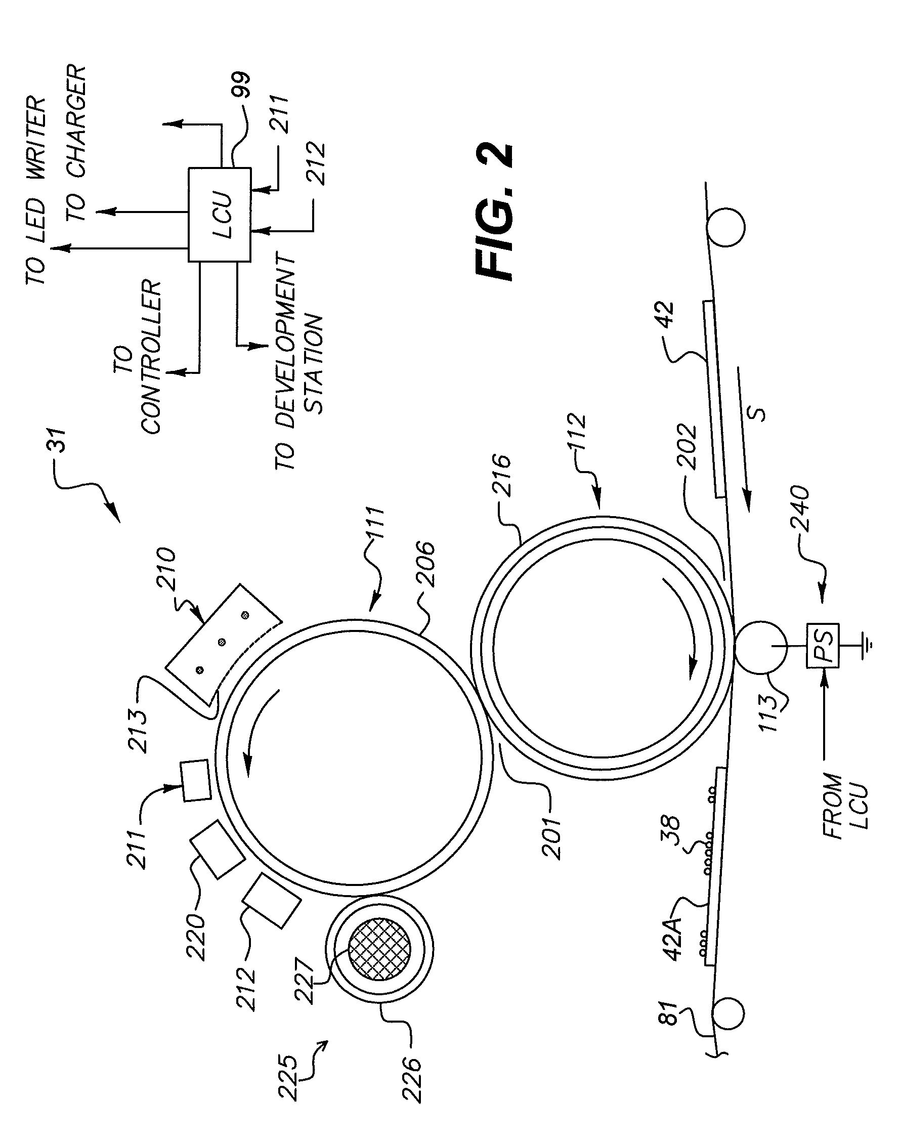
[0027]The electrophotographic (EP) printing process can be embodied in devices including printers, copiers, scanners, and facsimiles, and analog or digital devices, all of which are referred to herein as “printers.” Various embodiments use electrostatographic printers such as electrophotographic printers that employ toner developed on an electrophotographic receiver, or ionographic printers and copiers that do not rely upon an electrophotographic receiver. Electrophotography and ionography are types of electrostatography (printing using electrostatic fields), which is a subset of electrography (printing using electric fields).

[0028]A digital reproduction printing system (“printer”) typically includes a digital front-end processor (DFE), a print engine (also referred to in the art as a “marking engine”) for applying toner to the receiver, and one or more post-printing finishing system(s) (e.g. a UV coating system, a glosser system, a laminator system, a sorting system, a binding syst...


PUM


Abstract

An electrophotographic (EP) printer for transferring a toner image to a receiver sheet has a tensioned rotatable transport web with a Young's modulus of at least 1 GPa. The transport web is wrapped around a compliant image-bearing member. A compressible, rotatable nip-forming member that is relatively less stiff than the image-bearing member is adjacent to the transport web on the opposite side thereof from the image-bearing member. A mount holds the nip-forming member against the image-bearing member, and permits the axis of rotation of the nip-forming member to move closer to or farther from the transport web. When the leading edge of the receiver on the web engages with the image-bearing member, the nip-forming member compresses. The axis of rotation of the nip-forming member translates by an amount less than the thickness of the receiver sheet minus the compression of the compliant coating of the image-bearing member.

Description

CROSS-REFERENCE TO RELATED APPLICATIONS[0001]Reference is made to commonly assigned, co-pending U.S. patent application Ser. No. 13 / 220,795 filed Aug. 30, 2011, entitled “Printer with Compressible and Incompressible Transfer Backups,” by Mark C. Zaretsky, et al., the disclosure of which is incorporated by reference herein.FIELD OF THE INVENTION[0002]This invention pertains to the field of printing and more particularly to improving image quality of various types of printed images.BACKGROUND OF THE INVENTION[0003]Printers are useful for producing printed images of a wide range of types. Printers print on receivers (or “imaging substrates”), such as pieces or sheets of paper or other planar media, glass, fabric, metal, or other objects. Printers typically operate using subtractive color: a substantially reflective receiver is overcoated image-wise with separations of cyan (C), magenta (M), yellow (Y), black (K), light black (Lk), and other colorants, one at a time.[0004]In various pri...

Claims


Application Information

Patent Timeline
Patent Type & Authority Patents(United States)
IPC IPC(8): G03G15/16
CPCG03G15/162G03G15/1685G03G15/167
Inventor ZARETSKY, MARK CAMERONKITTLESON, ANDREW PETERHUNTINGTON, JAMES H.YOUNG, TIMOTHY JOHNLIVADAS, JERRY EUGENE
Owner EASTMAN KODAK CO
Learn More