Worn display system and method without requiring real time tracking for boresight precision

a display system and boresight technology, applied in the field of displays, can solve the problems of requiring optical components that can be heavy, expensive, and take up space in the cockpit, and the head tracking equipment increases the size and cost of head worn displays

Active Publication Date: 2014-02-25
ROCKWELL COLLINS INC
View PDF47 Cites 91 Cited by
  • Summary
  • Abstract
  • Description
  • Claims
  • Application Information

AI Technical Summary

Problems solved by technology

Conventional head-up displays require optical components that can be heavy, expensive, and take up space in the cockpit.
Head tracking equipment increases the size and cost of head worn displays.

Method used


Image

  • Worn display system and method without requiring real time tracking for boresight precision
  • Worn display system and method without requiring real time tracking for boresight precision
  • Worn display system and method without requiring real time tracking for boresight precision

Examples


Embodiment Construction

[0021]Before describing in detail the particular improved system and method, it should be observed that the invention includes, but is not limited to, a novel structural combination of optical components and not in the particular detailed configurations thereof. Accordingly, the structure, methods, functions, control, and arrangement of components have been illustrated in the drawings by readily understandable block representations and schematic drawings, in order not to obscure the disclosure with structural details which will be readily apparent to those skilled in the art, having the benefit of the description herein. The Figures are not drawn to scale. Further, the invention is not limited to the particular embodiments depicted in the exemplary diagrams, but should be construed in accordance with the language in the claims.

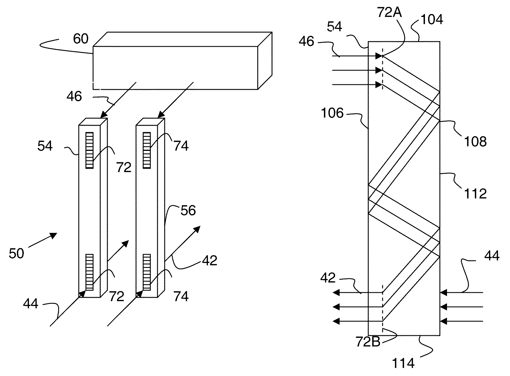
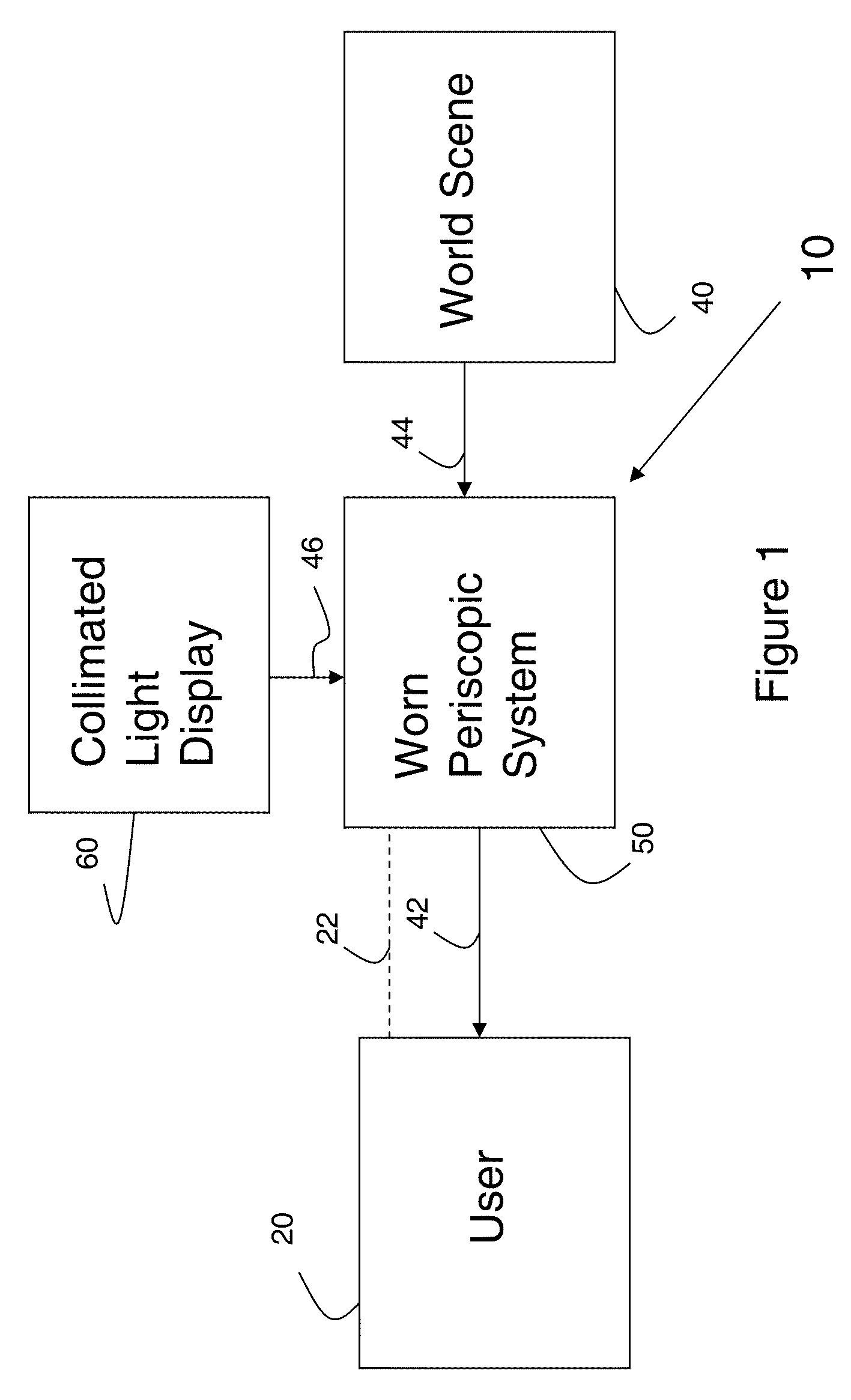
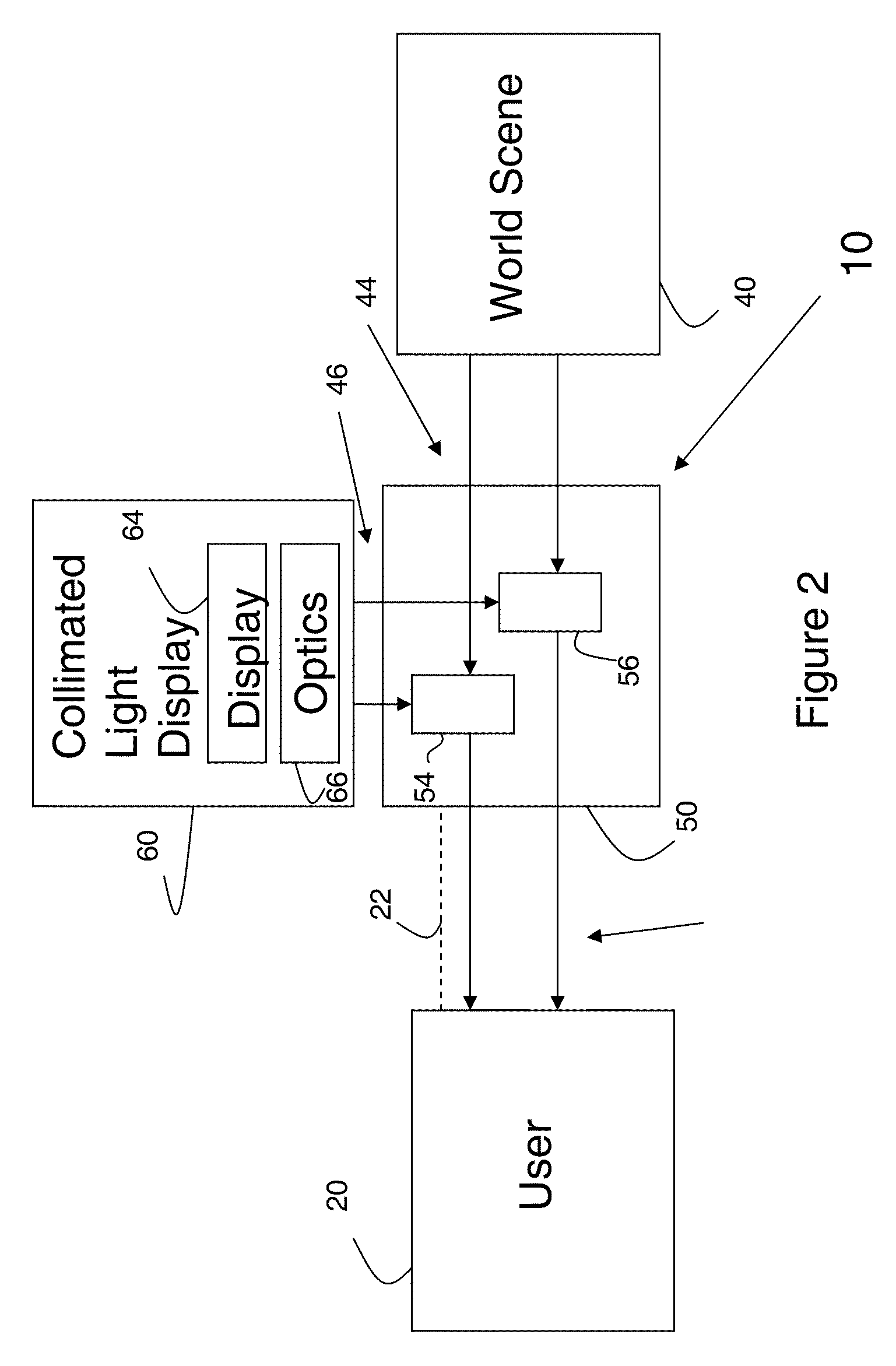
[0022]With reference to FIG. 1, a wearable display system 10 is preferably configured as a head worn display (HWD). System 10 is described below for use in a ...


PUM


Abstract

A worn display, such as a head worn display, includes a projector and a periscopic system configured to be wearable. The periscopic system includes at least one diffraction grating member. The member includes an input end for receiving an image from a projector and a combiner end for receiving light from a scene and providing the image received at the input end and the light received from the outside scene to the user. The head worn display can be used in aircraft applications to provide guidance information to a pilot.

Description

BACKGROUND OF THE INVENTION[0001]The present specification relates to displays. More particularly, the present specification relates to a worn display, such as a head worn display (HWD) also known as a head-mounted display.[0002]Display systems have been used to provide information to users for various applications. In aircraft applications, displays can provide precision guidance information to a pilot. For example, head-up displays (HUDs) superimpose images from two sources, the outside world and a second source for presentation to the pilot. Head-up displays are especially useful in aircraft because they allow the pilot to view information related to flight parameters without diverting attention from the view of the outside world through the windshield. Conventional head-up displays require optical components that can be heavy, expensive, and take up space in the cockpit.[0003]Worn displays such as head worn displays have similarly been used in aircraft applications to allow a pi...

Claims


Application Information

Patent Timeline
Patent Type & Authority Patents(United States)
IPC IPC(8): G02B27/14G02B23/08
CPCG02B27/14G02B27/017G02B2027/0138G02B2027/0187G02B23/08G02B5/18G02B27/0172G02B27/4205
Inventor BROWN, ROBERT D.ROBBINS, STEVEN J.RAYNAL, FRANCOIS
Owner ROCKWELL COLLINS INC
Why Eureka
Try Eureka