
Bipod-mounted mortar fire control system

a control system and mortar technology, applied in the field of mortar systems, can solve the problems of no single mounting method that may be used, and unable to meet the requirements of the application

Inactive Publication Date: 2014-03-04
UNITED STATES OF AMERICA THE AS REPRESENTED BY THE SEC OF THE ARMY
View PDF2 Cites 2 Cited by
  • Summary
  • Abstract
  • Description
  • Claims
  • Application Information

AI Technical Summary

Benefits of technology

The invention is about a device for mounting an electronics unit to a portion of a bipod that is not fixed for movement with a cannon. The apparatus includes mounting brackets, support rails, support rods, and a guide rod housing. This allows for the safe mounting of the electronics unit to the bipod without interfering with the movement of the cannon. Additionally, the patent describes a mortar bipod that includes a traverse yoke for fixing fire control guide rods. The invention also includes a method of isolating the electronics unit from firing loads of the cannon by using a bipod that is not fixed for movement with the cannon.

Problems solved by technology

Impact with the firing pin ignites the propellant behind the projectile, creating tremendous pressures and ejecting the projectile out of the cannon.
The extreme accelerations experienced by a mortar system during firing may damage sensitive DFCS components.
However, there is no single mounting method that may be used with both the M1064 and M326 platforms.
In addition, neither method allows one to easily remove the fire control mounting hardware from the cannon after a misfire.
Because both known mounting methods interface directly with cannon, those methods have precise torque requirements that if not adhered to, can disrupt the functionality of the cannon.
Because the harshest firing environment is in the dismounted configuration, the M326 Quick Stow DFCS mount has a very large size and weight.
The large size and weight of the mount are needed to meet the shock requirements for DFCS, but are otherwise very undesirable.

Method used


Image

  • Bipod-mounted mortar fire control system
  • Bipod-mounted mortar fire control system
  • Bipod-mounted mortar fire control system

Examples


Embodiment Construction

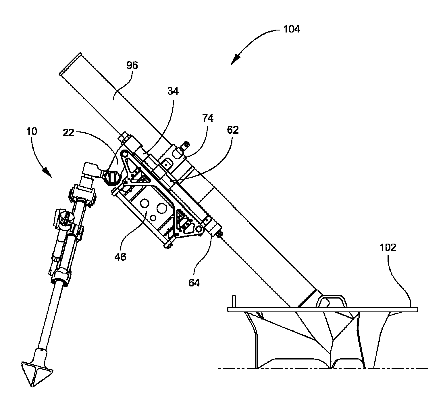
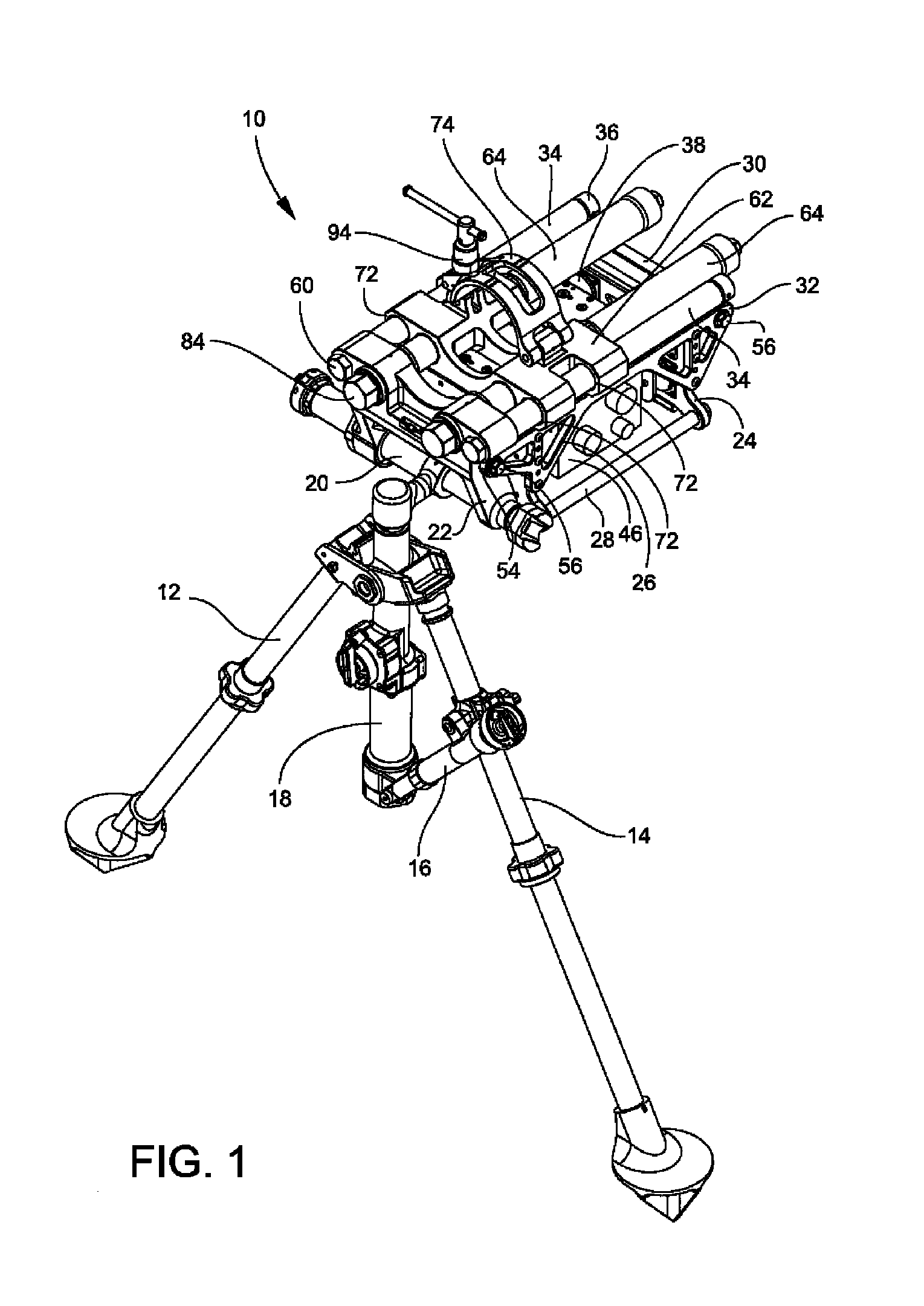
[0027]A mortar bipod may include an apparatus for mounting mortar fire control hardware or other electronics which are required to be co-oriented with the mortar cannon tube. The bipod may be axially buffered from the cannon tube and its associated recoil shock. Compared to mounting the electronics to a buffered assembly that is attached directly to the cannon tube, mounting the electronics to a buffered bipod may eliminate the need to remove the electronics from the cannon tube when the cannon tube is removed, such as in misfire procedures. In prior art mortar systems, the fire control hardware, such as a pointing device or DFCS, may be mounted to the cannon tube.

[0028]The novel mortar bipod may better isolate the DFCS from the harsh firing environment and may minimize the shock loads experienced by the DFCS. The novel mortar bipod may also weigh much less than prior art bipods. For example, an embodiment of the novel mortar bipod for use with a 120 mm mortar system may weigh about...


PUM


Abstract

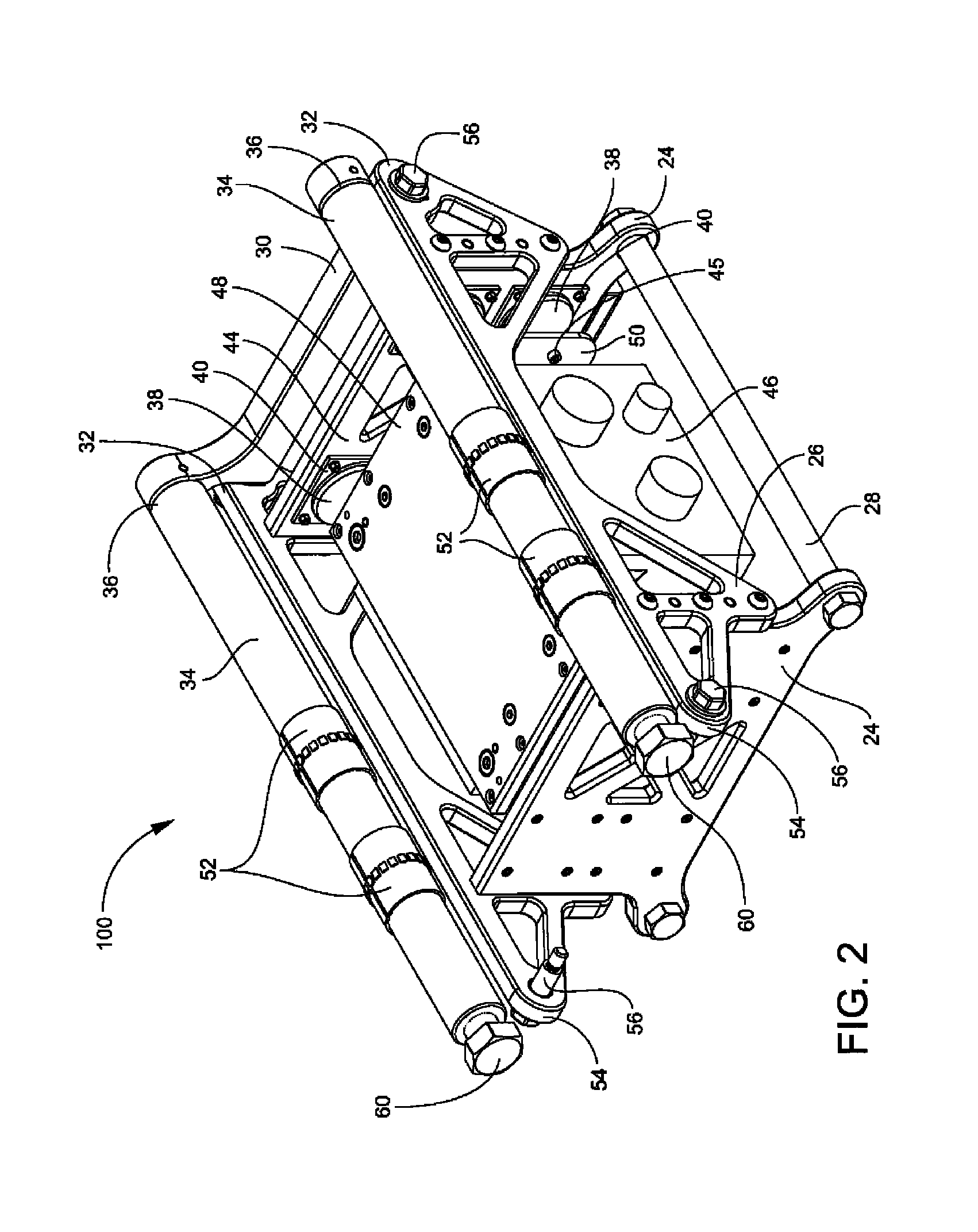
An apparatus for mounting an electronics unit, such as a digital pointing device, to a mortar bipod may include a pair of spaced-apart, generally parallel mounting brackets having respective inner faces. A pair of support rails may be fixed to opposite outer edges of the mounting brackets. A pair of support rods may be fixed between opposite lower portions of the mounting brackets. A lower guide rod housing may be fixed to first ends of the support rails. A pair of fire control guide rods may have first ends fixed to the lower guide rod housing. A plurality of shock mounts may have respective bases and tops. The shock mount bases may be fixed to the respective inner faces of the mounting brackets. The electronics unit may include a top plate fixed thereto. A pair of side plates may be fixed to the top plate. The side plates may extend generally perpendicularly from the top plate. The tops of the shock mounts may be fixed to the side plates.

Description

STATEMENT OF GOVERNMENT INTEREST[0001]The inventions described herein may be manufactured, used and licensed by or for the U.S. Government for U.S. Government purposes.BACKGROUND OF THE INVENTION[0002]The invention relates in general to mortar systems and in particular to the mounting of digital fire control systems for mortar systems.[0003]During firing of a mortar system, a mortar round is dropped into the top of a cannon and slides down until it hits a firing pin at the bottom. Impact with the firing pin ignites the propellant behind the projectile, creating tremendous pressures and ejecting the projectile out of the cannon. The large pressure forces react against the pressure vessel or cannon and translate into the baseplate, thereby forcing both the cannon and baseplate to move into the ground surface. This movement or burying effect into the ground is typical of all dismounted mortar systems.[0004]During the above firing procedure, the bipod is responsible for supporting and s...

Claims


Application Information

Patent Timeline
IPC IPC(8): F41F1/06
CPCF41A23/08F41A25/12F41F1/06
Inventor HART, JEFFERYMONTANIO, SCOTTLEWIN, BENJAMINMCDONALD, STEVENGALLIANO, RAULGRAVINA, JOHN N.
Owner UNITED STATES OF AMERICA THE AS REPRESENTED BY THE SEC OF THE ARMY
Learn More