Stable offshore floating depot

a floating depot and stable technology, applied in the field of offshore buoyant vessels, can solve the problems of fatigue and failure, acceleration, displacement and oscillation of the structure, and the major operating cost of the transportation of support and supplies from on-shore facilities, and achieve the effect of exceptional heave damping characteristics

Active Publication Date: 2014-03-04
JURONG SHIPYARD
View PDF55 Cites 36 Cited by
  • Summary
  • Abstract
  • Description
  • Claims
  • Application Information

AI Technical Summary

Benefits of technology

[0022]A primary object of the invention is to provide a buoyant offshore depot or terminal characterized by all of the following advantageous attributes: Symmetry of the hull about a vertical axis; the center of gravity located below the center of buoyancy for inherent stability without the requirement for complex retractable columns or the like, exceptional heave damping characteristics without the requirement for mooring with vertical tendons, and a design that provides for quayside integration of the superstructure and “right-side-up” transit to the installation site, including the capability to transit through shallow waters.
[0023]Another object of the invention is to provide a buoyant offshore depot or terminal that may be strategically positioned nearby one or more offshore platforms to act as a safe shelter and distribution point for supply boats, helicopters, stores, and personnel.
[0024]Another object of the invention is to provide a buoyant offshore depot or terminal with improved pitch, roll and heave resistance.

Problems solved by technology

In offshore work, on drilling and production platforms for example, a major operating cost arises from the transportation of support and supplies from on-shore facilities.
Such supply lines are subject to adverse weather and sea states, which have greater effect the farther the supplies must travel.
These environmental forces result in accelerations, displacements and oscillatory motions of the structure.
Heave motions can create tension variations in mooring systems, which can cause fatigue and failure.
Large heave motions increase danger in launching and recovery of small boats and helicopters and loading and offloading stores and personnel.
However, tension leg platforms are costly structures and, accordingly, are not feasible for use in all situations.
However, the heave seakeeping characteristics of a large waterplane area in the wave zone are generally undesirable.
The combined weight of the superstructure, hull, payload, ballast and other elements may be arranged to lower the center of gravity, but such an arrangement may be difficult to achieve.
Although the heave seakeeping characteristics of self-stabilizing floating structures are generally inferior to those of tendon-based platforms, self-stabilizing structures may nonetheless be preferable in many situations due to higher costs of tendon-based structures.
However, due to the large size of the spar hull, fabrication, transportation and installation costs are increased.
However, the center column adds complexity and cost to the construction of the platform.
Although, the Smedal structure has a circumferential recess formed about the hull near the keel for pitch and roll damping, the location and profile of such a recess has little effect in dampening heave.

Method used


Image

  • Stable offshore floating depot
  • Stable offshore floating depot
  • Stable offshore floating depot

Examples


Embodiment Construction

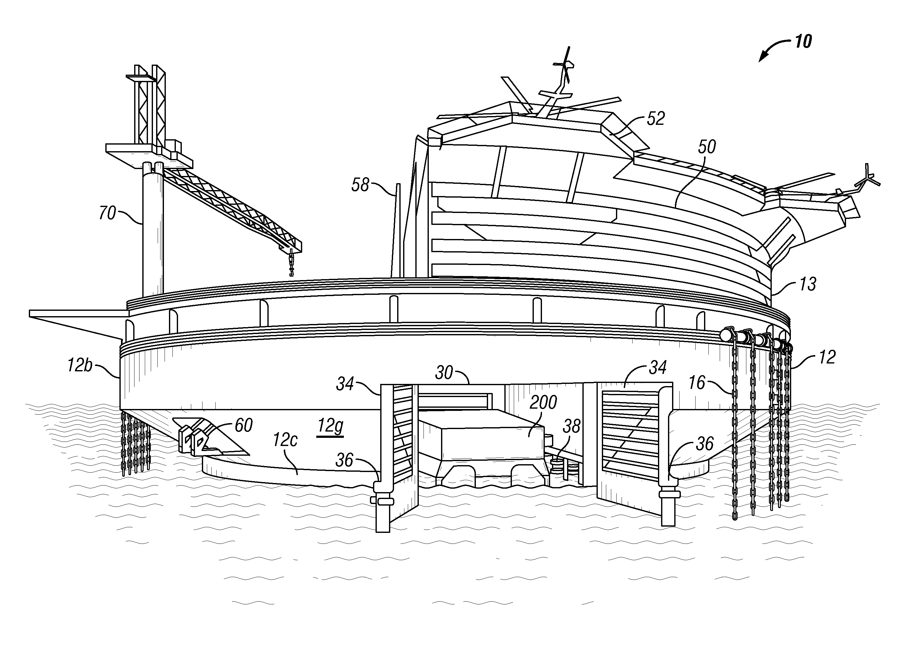
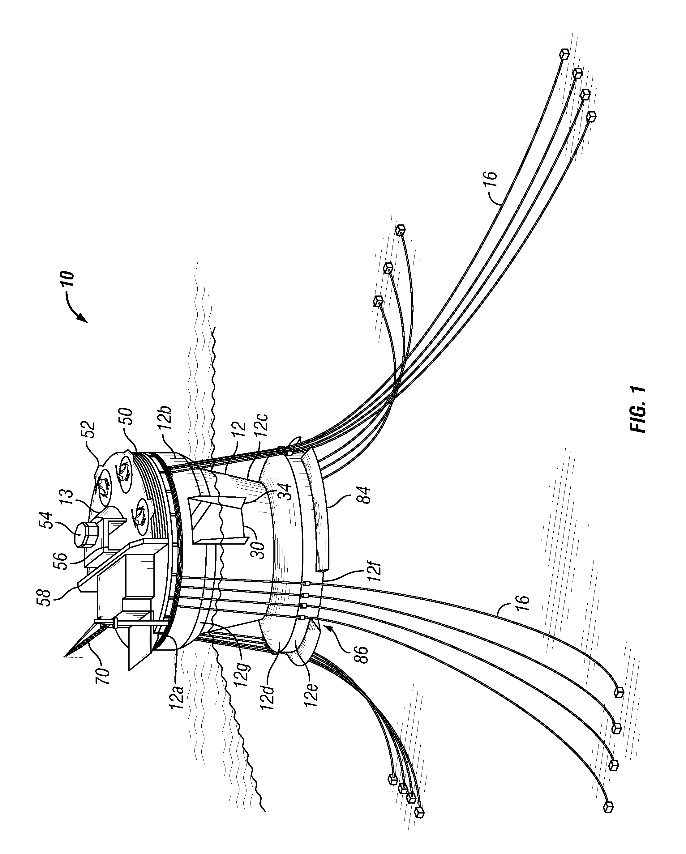
[0044]FIG. 1 illustrates a buoyant offshore depot 10 for operationally supporting offshore exploration, drilling, production, and storage installations according to a preferred embodiment of the invention. Offshore depot 10 includes a buoyant hull 12, which may carry a superstructure 13 thereon. Superstructure 13 may include a diverse collection of equipment and structures, such as living quarters for a crew, equipment storage, a heliport, and a myriad of other structures, systems, and equipment, depending on the type of offshore operations to be supported. Hull 12 is preferably moored to the seafloor by a number of catenary mooring lines 16.

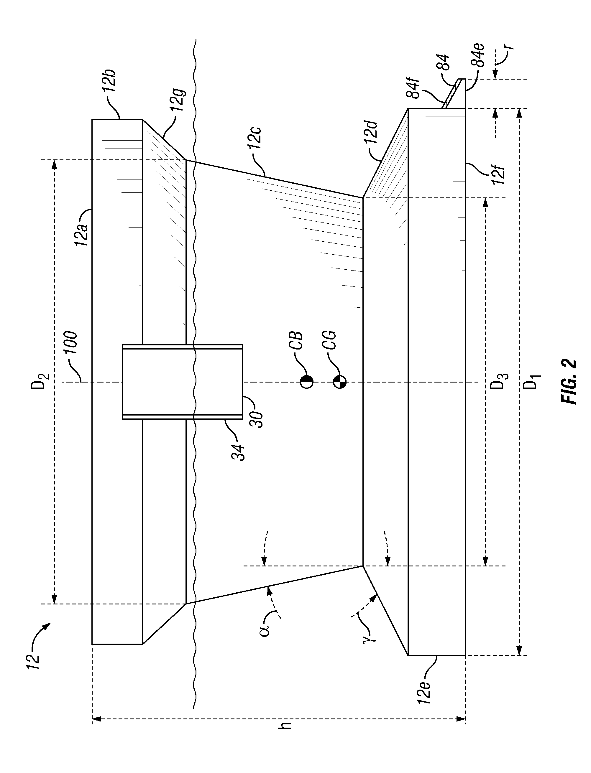
[0045]FIG. 2 is a simplified view of the vertical profile of hull 12 according to a preferred embodiment of the invention. Referring both to FIGS. 1 and 2, in a preferred embodiment, hull 12 of offshore depot 10 has a circular main deck 12a, an upper cylindrical side section 12b extending downwardly from deck 12a, an inwardly-tapering upper frus...


PUM


Abstract

An offshore depot having a vertically symmetric hull, an upper inwardly-tapered wall and a lower outwardly-tapered wall that produce significant heave damping in response to heavy wave action. Ballast is added to the lower and outermost portions of the hull to lower the center of gravity below the center of buoyancy. The offshore depot includes a tunnel formed within or through the hull at the waterline that provides a sheltered area inside the hull for safe and easy launching / docking of boats and embarkation / debarkation of personnel. When the watertight tunnel doors are all shut, the tunnel may be drained to create a dry dock environment within the hull. The offshore depot includes berthing and dinning accommodations, medical facilities, workshops, machine shops, a heliport, and the like.

Description

CROSS REFERENCE TO RELATED APPLICATION[0001]This application is a continuation-in-part of U.S. patent application Ser. No. 12 / 914,709 filed on Oct. 28, 2010, now U.S. Pat. No. 8,251,003, which is incorporated herein by reference and which claims the benefit of U.S. Provisional Application No. 61 / 259,201 filed on Nov. 8, 2009 and U.S. Provisional Application No. 61 / 262,533 filed on Nov. 18, 2009. This application also claims the benefit of U.S. Provisional Application No. 61 / 521,701 filed on Aug. 9, 2011, which is incorporated herein by reference.BACKGROUND OF THE INVENTION[0002]1. Field of the Invention[0003]This present invention pertains generally to offshore buoyant vessels, platforms, caissons, buoys, spars, or other structures used for supporting offshore oil and gas operations. In particular, the present invention relates to a stable moored offshore terminal, such as would be used for safe handling, staging, and transportation of personnel, supplies, boats, and helicopters.[00...

Claims


Application Information

Patent Timeline
Patent Type & Authority Patents(United States)
IPC IPC(8): B63B35/44
CPCB63B22/02B63G11/00B63B35/44B63B1/041B63B21/50B63B2241/06B63B2035/446B63B35/4413B63H25/42B63B2035/448B63B2039/067B63B2003/147B63B2231/02B63B39/00B63B39/02B63B2021/003B63B2035/4473
Inventor VANDENWORM, NICOLAAS, J.
Owner JURONG SHIPYARD
Why Eureka
Try Eureka