Linear flexure bearing

a technology of linear flexure and bearing, which is applied in the direction of sliding contact bearings, washing machines, mechanical equipment, etc., can solve the problem of inability to operate in parallel

Active Publication Date: 2014-03-04
VALOIS MICHAEL
View PDF11 Cites 3 Cited by
  • Summary
  • Abstract
  • Description
  • Claims
  • Application Information

AI Technical Summary

Problems solved by technology

This makes it impossible for them to operate in parallel.

Method used


Image

  • Linear flexure bearing
  • Linear flexure bearing
  • Linear flexure bearing

Examples


Embodiment Construction

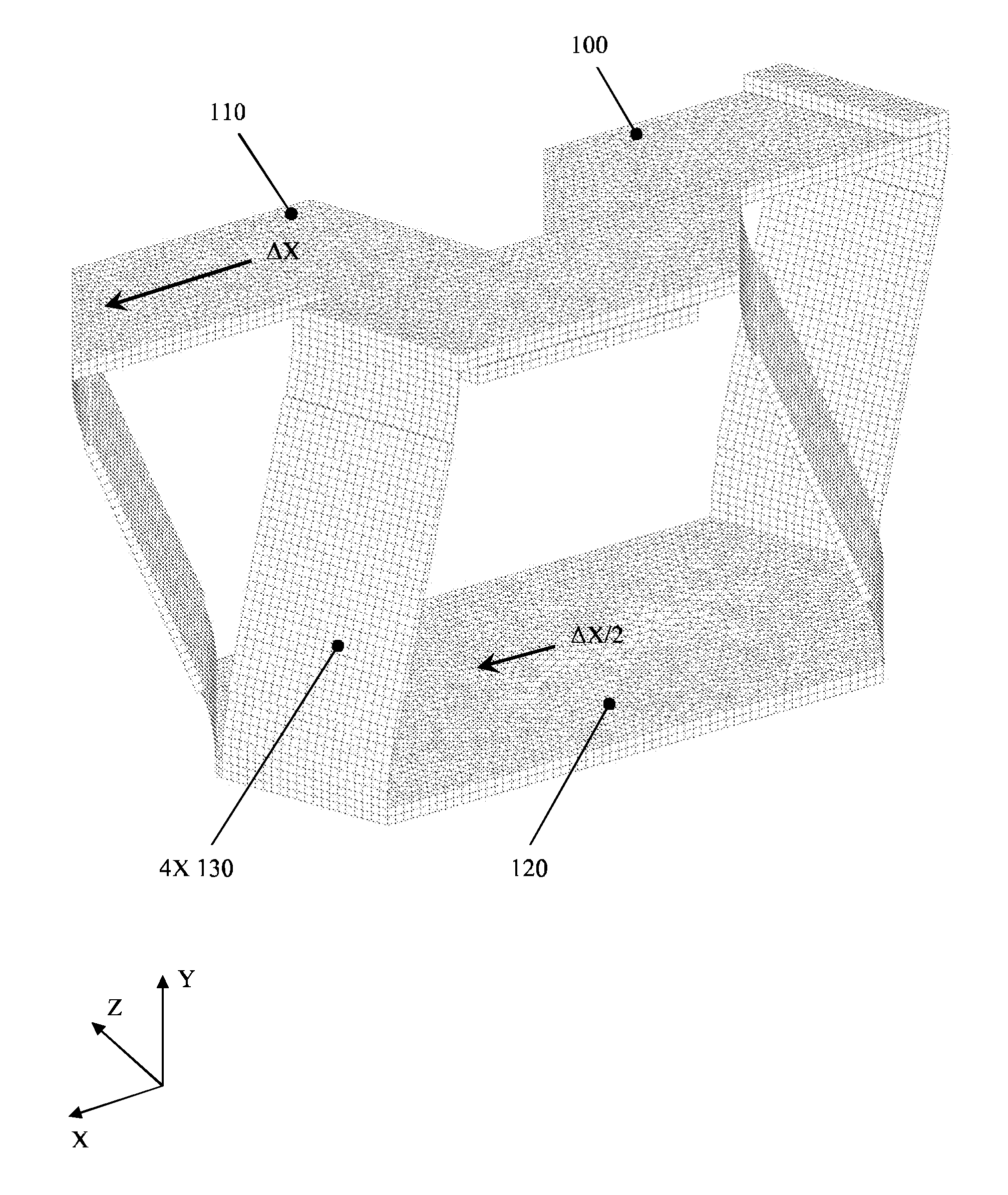
[0021]The proposed linear flexure bearing concept is shown at mid travel in FIG. 9. It is composed of two simple parallel flexure translation bearings. The first is defined by the fixed member 100 and the intermediate member 120 connected by one pair of flexure members 130. The second is defined by the active member 110 and the intermediate member 120 connected by another pair of flexure members 130. The two simple parallel flexure translation bearings share the intermediate member. The four flexure members 130 share the same stiffness and dimensions.

[0022]The load path is the same as in a conventional compound linear flexure bearing, so when the active member 110 is moved in the X direction the two simple parallel flexure translation bearings still operate in the same fashion, except they do not move parallel to each other as shown in FIG. 10. The flexure member pair between the fixed member 100 and intermediate member 120 guides the intermediate member 120 along a straight path at...


PUM


Abstract

This compound linear flexure bearing incorporates a simple but unique flexure arrangement which inherently allows stable long travel operation. The flexure arrangement passively constrains all degrees of freedom except translation along the bearing axis while also compensating for flexure foreshortening. This design permits large displacement, low operating stress, low operating force, and high stiffness in the five noncompliant degrees of freedom. The linear flexure bearing described herein has applications in precision mechanics, particularly opto-mechanics. Specific applications include but are not limited to wafer and reticle positioning stages used in microlithography systems, optic translation and scanning mechanisms used in tactical and spaceborne systems, as well as flip-in mechanisms used in multiple field of view optical systems.

Description

CROSS-REFERENCE TO RELATED APPLICATIONS[0001]Not ApplicableFEDERALLY SPONSORED RESEARCH OR DEVELOPMENT[0002]Not ApplicableREFERENCE TO SEQUENCE LISTING[0003]Not ApplicableBACKGROUND OF THE INVENTION[0004]This invention generally relates to a flexure based linear guide bearing. Flexures have been used successfully in motion systems for centuries. Since they operate by bending, not rolling or sliding, flexures have the inherent advantage of friction-free motion. This key feature allows engineers to build positioning systems with nearly unlimited precision and accuracy. They are also easily fabricated using readily available materials and common methods. However, even with these desirable attributes there are very few flexure based linear bearings available commercially. Therefore, it is common practice for an engineer to design custom flexure systems when developing a new mechanism. The linear flexure bearing described herein is particularly well suited for integration into precision ...

Claims


Application Information

Patent Timeline
Patent Type & Authority Patents(United States)
IPC IPC(8): F16B43/00
CPCF16F3/02
Inventor VALOIS, MICHAEL
Owner VALOIS MICHAEL
Why Eureka
Try Eureka