Integrated circuit, wireless communication unit and method for a differential interface for an envelope tracking signal

a technology of integrated circuits and differential interfaces, applied in the direction of amplifiers, dc amplifiers with modulator-demodulator, gain control, etc., can solve the problems of low efficiency of dc to rf power conversion, poor power amplifier efficiency, and inability to meet the needs of portable (subscriber) wireless communication units, etc., to achieve alleviation or eliminate one

Active Publication Date: 2014-03-04
MEDIATEK SINGAPORE PTE LTD SINGAPORE
View PDF29 Cites 13 Cited by
  • Summary
  • Abstract
  • Description
  • Claims
  • Application Information

AI Technical Summary

Problems solved by technology

Since the envelopes of these linear modulation schemes fluctuate, this phenomenon results in the average power delivered to the antenna being significantly lower than the maximum power, potentially leading to poor efficiency of the power amplifier.
However, the active devices used within a typical RF amplifying device are inherently non-linear by nature.
This ‘linear’ mode of operation provides a low efficiency of DC to RF power conversion, which is unacceptable for portable (subscriber) wireless communication units.
Furthermore, such low efficiency performance is also recognised as being problematic for the base stations.
This is in contrast to the previously often-used constant envelope modulation schemes and can result in significant reduction in power efficiency and linearity.
In the fixed supply case, excess PA supply voltage headroom 110 is used (and thereby potentially wasted), irrespective of the nature of the modulated RF waveform being amplified.
However, it is also known that for high bandwidth signals, accurate tracking of the RF envelope is difficult to achieve in practical implementations.
However, the simplified modulator circuit 300 is not ideal in that the input signal corresponding to the envelope is strictly positive.
Thus, the potential headroom benefits due to employing a differential input signal (i.e. both positive and negative portions of the signal) are not realized, even when employing additional circuit techniques to minimize DC offset and / or reduce noise.
A further disadvantage in the simplified modulator circuit 300 is that the input AC envelope signal is not symmetrical around a mean value.
Often, complex techniques such as de-troughing (or other signal mapping techniques) may then be required to increase the asymmetry of the modulator signal, thereby increasing the complexity of circuit 300.

Method used


Image

  • Integrated circuit, wireless communication unit and method for a differential interface for an envelope tracking signal
  • Integrated circuit, wireless communication unit and method for a differential interface for an envelope tracking signal
  • Integrated circuit, wireless communication unit and method for a differential interface for an envelope tracking signal

Examples


Embodiment Construction

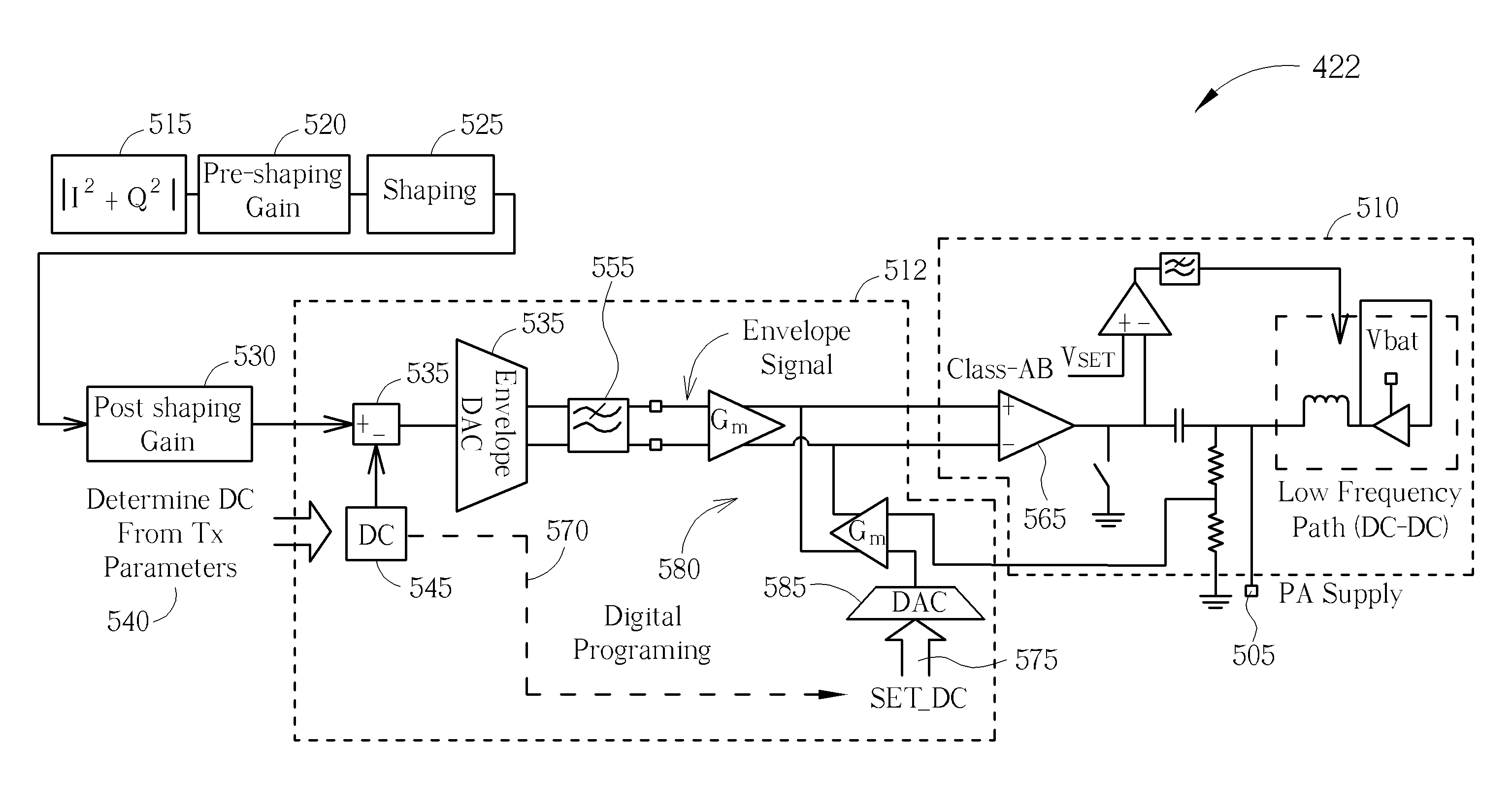
[0025]Examples of the invention will be described in terms of one or more integrated circuits for use in a wireless communication unit, such as user equipment in third generation partnership project (3GPP™) parlance. However, it will be appreciated by a skilled artisan that the inventive concept herein described may be embodied in any type of integrated circuit, wireless communication unit or wireless transmitter that could benefit from improved linearity and efficiency using a differential circuit. In some examples of the invention, a circuit design for interfacing an Envelope Tracking amplifier (supply modulator) to the envelope extraction path (Envelope extraction and DAC) is described. The circuit design may compensate for the strictly positive envelope modulated signal produced by the envelope extraction path. One example of the described circuit design may remove a fixed DC component from the positive envelope modulated signal, thereby increasing signal headroom used by subseq...


PUM


Abstract

An integrated circuit for providing a differential interface for an envelope tracking signal is described. The integrated circuit includes a subtraction module having a first input for receiving a digital envelope tracking signal and a second input for receiving a second signal, wherein the subtraction module is arranged to subtract the second signal from the digital envelope tracking signal and produce an envelope tracking signal with a reduced average direct current (DC) component; a digital-to-analog converter (DAC) arranged to receive the envelope tracking signal with the reduced average DC component and produce a differential analog version thereof; and a modulator operably coupled to a differential output of the DAC, wherein the modulator comprises a DC input point arranged to insert a DC component into the differential analog version of the envelope tracking signal.

Description

CROSS REFERENCE TO RELATED APPLICATIONS[0001]This is a continuation-in-part (CIP) of co-pending U.S. application Ser. No. 13 / 345,760 (filed on Jan. 9, 2012), which claims the benefit of U.S. provisional application No. 61 / 438,347 (filed on Feb. 1, 2011) and U.S. provisional application No. 61 / 563,316 (filed on Nov. 23, 2011), and this CIP application further claims the benefit of U.S. provisional application No. 61 / 549,491 (filed on Oct. 20, 2011). The entire contents of these related applications are incorporated herein by reference.BACKGROUND OF THE INVENTION[0002]The field of this invention relates to wireless communication units, integrated circuits, transmitter architectures and in particular circuits for providing a differential to single ended conversion of signals. The invention is applicable to, but not limited to, envelope tracking using a differential circuit configuration and a method therefor.[0003]A primary application of the present invention is in the field of radio ...

Claims


Application Information

Patent Timeline
Patent Type & Authority Patents(United States)
IPC IPC(8): H03G3/20
CPCH03F2200/429H03F1/0238H03F3/191H03F2200/432H03G1/0005H03M1/66
Inventor STRANGE, JONATHAN RICHARDFOWERS, PAUL
Owner MEDIATEK SINGAPORE PTE LTD SINGAPORE
Why Eureka
Try Eureka