

Driving method to neutralize grey level shift for electrophoretic displays
a technology of electrophoretic display and grey level shift, which is applied in the field of electrophoretic display, can solve the problems of grey level shift, negative affecting the performance of electrophoretic display, and the decline of the optical response speed of the display, and achieve the effect of neutralizing the grey level shi
- Summary
- Abstract
- Description
- Claims
- Application Information
AI Technical Summary
Benefits of technology
Problems solved by technology
Method used
Image

Examples
example 1
Mono-Polar Waveforms
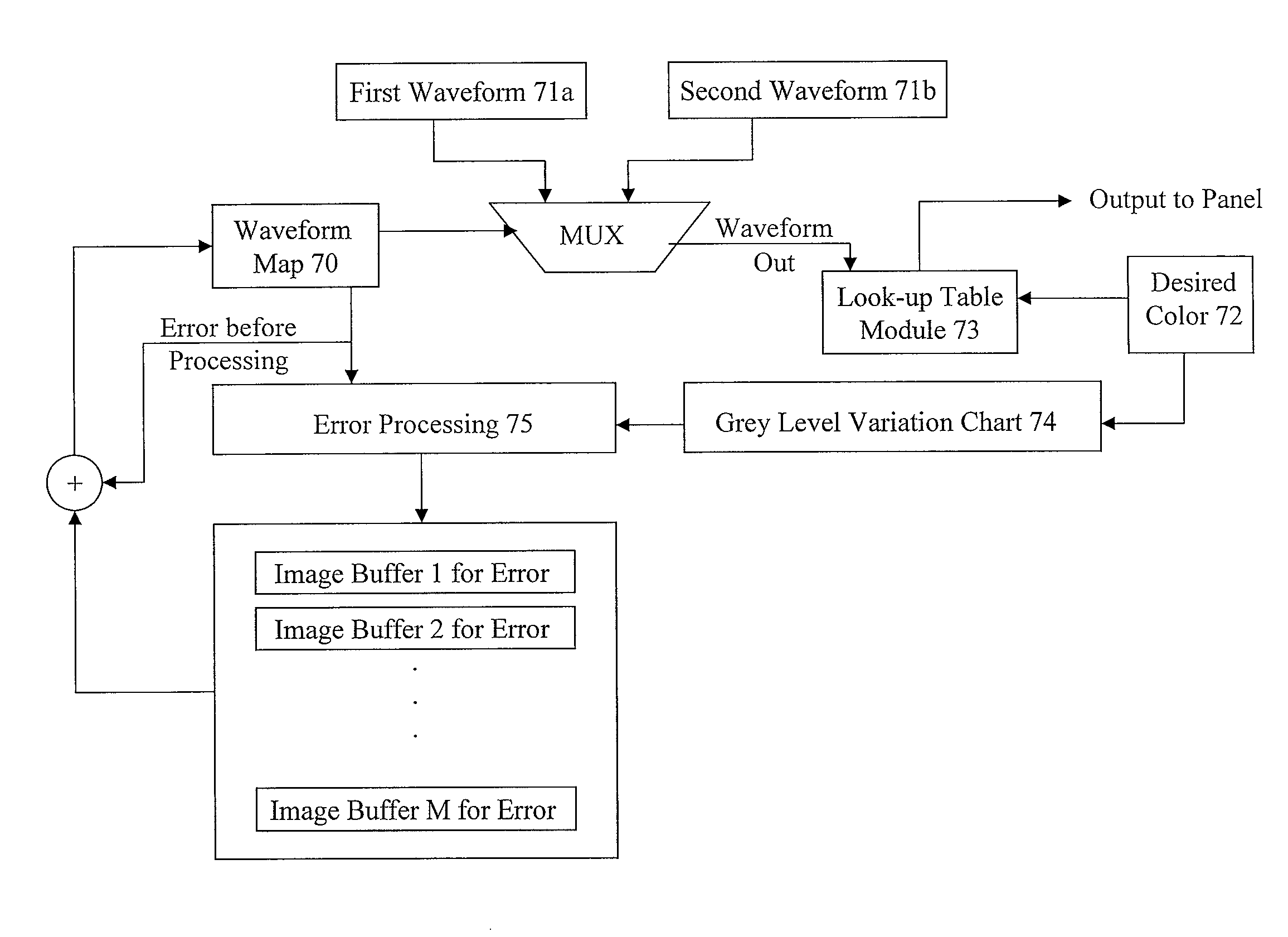
[0076]FIG. 3 shows an example of the first and second waveforms referred to in the methods as described. As shown, the two waveforms marked as “WG” and “KG” waveforms have three driving phases (I, II and III). Each driving phase has a driving time of equal length, T, which is sufficiently long to drive a pixel to a full white or a full black state, regardless of the previous color state.
[0077]For illustration purpose, FIG. 3 represents an electrophoretic fluid comprising positively charged white pigment particles dispersed in a black solvent.
[0078]The common electrode is applied a voltage of −V, +V and −V during Phase I, II and III, respectively.
[0079]For the WG waveform, during Phase I, the common electrode is applied a voltage of −V and the pixel electrode is applied a voltage of +V, resulting a driving voltage of +2V and as a result, the positively charged white pigment particles move to be near or at the common electrode, causing the pixel to be seen in a whi...
example 2
A Grey Level Variation Chart
[0100]
IntendedWG WaveformKG WaveformGreyInitialDegradedInitial DegradedLevelActualActualActualActual00000140824102511096320369150872641181971202551452101344261662181585871742201717281872301821019194232197112102082342101401122023621515112225236224177132322382291881423523823520715255255255255
[0101]In this example, grey level 0 indicates a full black state and grey level 15 indicates a full white state. When expressed in a grey scale of 256 levels, similarly, level 0 indicates a full black state and level 255 indicates a full white state.
[0102]The chart also shows that there may be a slight variation in the initial state between the WG and the KG waveforms, when expanded to a higher order. For example, for the intended grey level 5, the WG waveform shows an initial state of 145 while the KG waveform shows an initial state of 134, expressed in a grey scale of 256. This is due to driving limitation of the platform (e.g., frame time); but this can be improved i...
example 3
Error Diffusion and Waveform Map
[0104]In this example, a display image of 12 pixels (A-L) is used to illustrate error diffusion.
[0105]
ABCDEFGHIJKL
[0106]The target image in this example is:
[0107]
A(10)B(5) C(4)D(7)E(5)F(4)G(8)H(7)I(5) J(4)K(5)L(5)
[0108]This means that in the target image, the 12 pixels A-L are driven to grey levels 10, 5, 4, 7, 5, 4, 8, 7, 5, 4, 5 and 5 respectively.
[0109]The following is a sequence of waveform maps showing how the method is carried out:[0110]Starting Waveform Map:
[0111]
A(0)B(0)C(0)D(0)E(0)F(0)G(0)H(0)I(0)J(0)K(0)L(0)[0112]Waveform Map after Pixel A is processed:
[0113]
A(WG)B(+11)C(0)D(0)E(0)F(0)G(+8) H(+2) I(0)J(0)K(0)L(0)[0114]Waveform Map after Pixel B is processed:
[0115]
A(WG)B(KG)C(−35)D(0)E(0)F(0)G(−7)H(−23)I(−5)J(0)K(0)L(0)[0116]Waveform Map after Pixel C is processed:
[0117]
A(WG)B(KG)C(WG)D(+19)E(0)F(0)G(−7)H(−15)I(+9)J(+3) K(0)L(0)
[0118]The Starting Waveform Map is the initial state of the waveform map in which each pixel shows a cumulative erro...
PUM
 Abstract
Description
Claims
Application Information