Belt plough

a belt-type, belt-type technology, applied in the direction of belt-type conveyors, conveyor parts, cleaning, etc., can solve the problems of spillage/cleanup problems downstream, material outside the alignment of the belt-type skirt, so as to improve the cleaning performance of the system, improve the cleaning performance, and avoid vibration

Inactive Publication Date: 2014-03-11
TASMAN WARAJAY
View PDF8 Cites 2 Cited by
  • Summary
  • Abstract
  • Description
  • Claims
  • Application Information

AI Technical Summary

Benefits of technology

[0018]In use, the blade rests on the belt substantially under its own dead weight, i.e. without any significant externally applied positive bias or force, and is free to move up and down relative to the support structure. This enables the blade to maintain contact with the belt and follow any undulations in the belt, and self-adjust for wear on the blade.
[0020]Advantageously, the belt plough assembly may optionally include a mechanism to enable the blade to jump obstructions on the surface of the belt, where such facility is desired in an installation. That mechanism may include an inclined floating servo link arm on the upstream side of the blade, extending downwardly and in a direction opposite to the direction of travel of the belt. The arm has a lower end portion adapted to rest on the belt and an upper end portion which operatively engages the blade. When the lower end of the arm encounters an obstruction on the belt, the impact force on the link arm is transmitted upwardly at an angle to the blade, causing the blade to lift. Once the obstruction has passed, the servo force disappears and the blade drops back onto the belt under gravity. A high-friction material can be interposed between the upper end of the link arm and the blade, to increase the frictional lift force applied to the blade.
[0021]The link arm is preferably about the same width as the blade in order to shield it from the obstructions on the belt. An additional advantage of the obstruction jumping mechanism is that, although the link arm exerts a much lower bearing pressure on the belt, the link arm still performs a pre-cleaning function before the belt reaches the blade.
[0023]Preferably, the blade is made of a suitable synthetic material. The construction of the plough assembly enables a blade made from synthetic material of specific gravity about 1.0 (which includes most plastics materials) to operate satisfactorily on a belt under the light bearing pressures created by the dead weight of a blade typically about 300 mm in height. It has been found that the wear rate of such a blade is acceptable, and the blade material does not accumulate heat from the frictional rubbing faster than it can be dissipated, i.e. the synthetic blade does not melt.
[0024]Advantageously, the plough assembly includes means for damping movements of the blade. In a preferred embodiment, a sheet of resiliently flexible rubber is attached to the blade, normally across the top of the blade and extending on both sides. The outer sections of the thin, soft rubber sheet sag or droop slightly under their own weight. Due to the inertial resistance of the outer sections to acceleration, they provide a counteracting force that dampens the vibration caused by the blade skipping along on the belt surface, thereby enabling it to maintain better contact with the belt at light bearing pressures. In this embodiment, the blade is still considered to rest on the belt substantially under its own dead weight as the sheet of resiliently flexible rubber does not add significant weight and / or can be considered to be part of the blade.
[0025]A conveyor belt installation typically comprises a plurality of plough assemblies as described above, located at outer longitudinal edge regions of the belt, either as opposed pairs or in staggered formation, and orientated to deflect material towards the centre of the belt. A series of belt plough assemblies can be installed at spaced locations longitudinally along the belt, to improve the cleaning performance of the system further.

Problems solved by technology

As material travels along on a conveyor it typically settles down and spreads out a bit, which means that even if material left the upstream loading station well contained with no material outside the skirting, by the time it gets to a downstream loading station there will often be a significant amount of material outside the alignment of the skirts.
(ii) belt ploughs located on the non material-carrying side (or return strand) of a conveyor belt to deflect or scrape off larger foreign objects that may get onto the belt, and could cause serious damage if they entered the nip point of a pulley.
If a belt plough does not remove or recover all the material from that part of the belt laterally outside the skirting, then it typically will lead to spillage / cleanup problems downstream.
It has been found that known belt ploughs do not perform this job properly and do not avoid spillage.
With known belt ploughs in fixed arrangements, the plough blade quickly wears and allows material to pass through.
In some arrangements, the whole plough assembly comprising the plough frame and blade(s) can “float” or pivot, but the applied bearing pressure or bias force on the belt surface then becomes excessive, along with the wear rate of the blades.
The top surface of the belt often becomes exposed to excessive wear at the same time.
Consequently, it is quite common for the skirting to be extended all the way between the loading points to avoid this spillage problem, adding significantly to the cost of construction.
However, there are also quite a large number of belts in service with mechanical clips joining the sections of belt, and these clips can protrude noticeably above the surface of the belt.
In addition, the surface of the belt may be damaged for other reasons, leading to surface irregularities.
Such raised belt joins and other surface irregularities can interfere with the operation of known plough blades.

Method used


Image

  • Belt plough
  • Belt plough
  • Belt plough

Examples


first embodiment

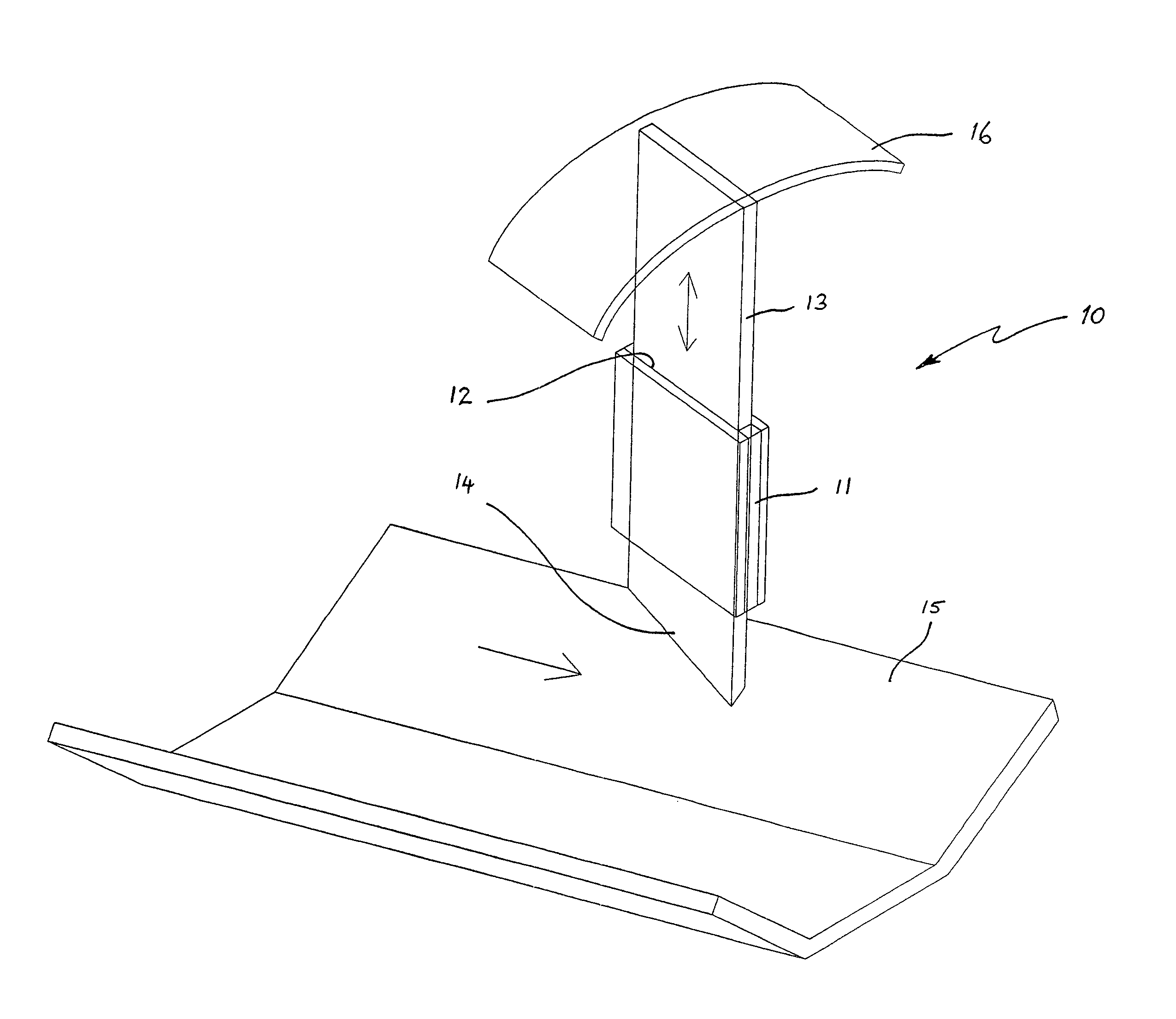
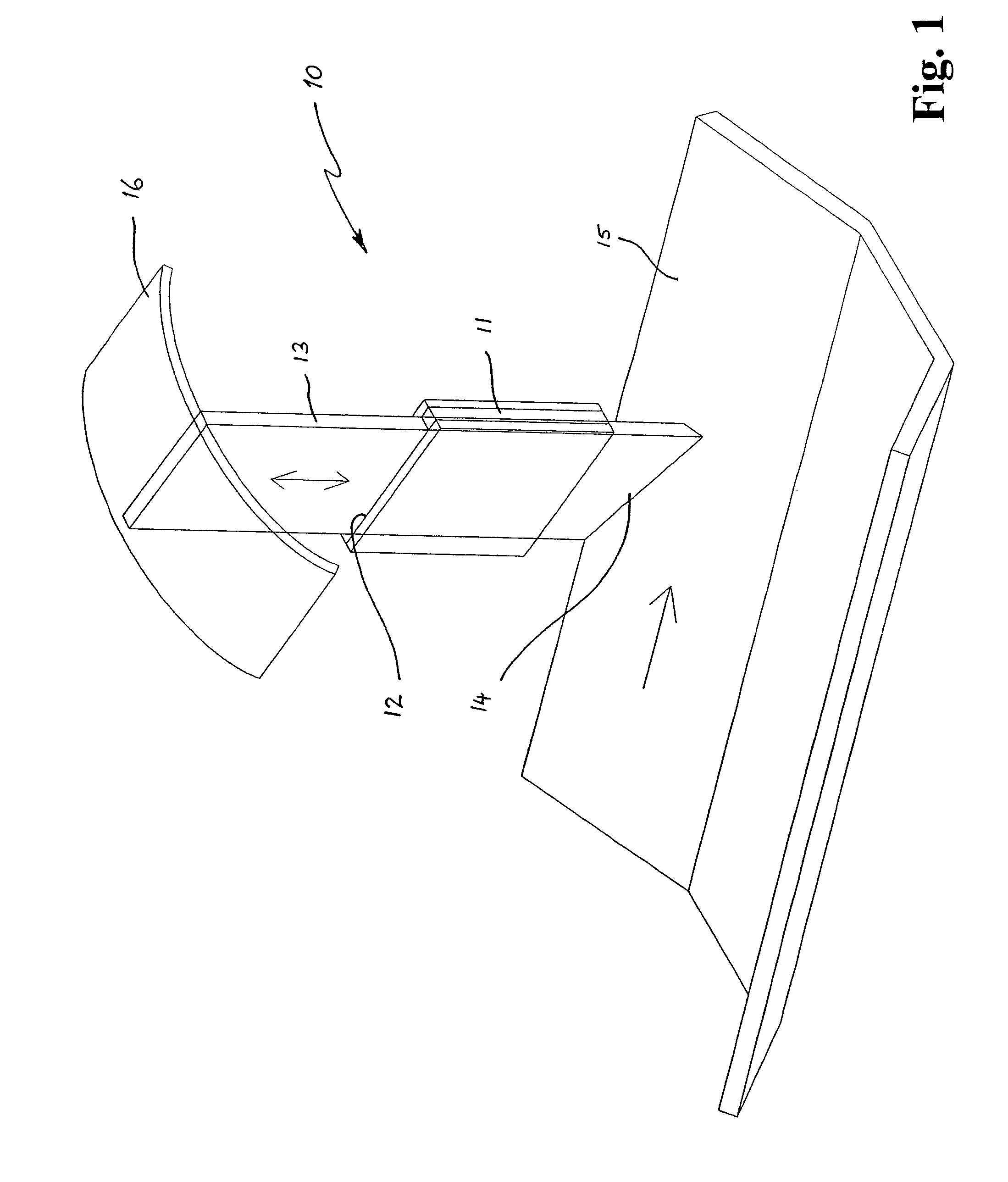
[0030]FIG. 1. illustrates a belt plough assembly 10 according to the invention. The belt plough assembly 10 comprises a housing 11 having a slot therein which extends substantially vertically. An upright plough blade 13 is located within the slot 12, and is able to slide up and down in the slot.

[0031]Although the slot 12 is shown vertical in FIG. 1, it will be appreciated that the slot may be orientated at an angle to the vertical, and the blade 13 will slide in an oblique direction. Generally however, the slot 12 and blade 13 will be mounted in a substantially upright orientation.

[0032]The bottom edge 14 of the blade 13 rests on the surface of a conveyor belt 15, primarily or substantially under the dead weight of the blade 13. No significant additional downward bias or force is applied to the blade. The blade is held in the housing such that the broad face of the blade 13 is angled obliquely to the direction of travel of the conveyor belt 15, so as to direct or deflect material on...

second embodiment

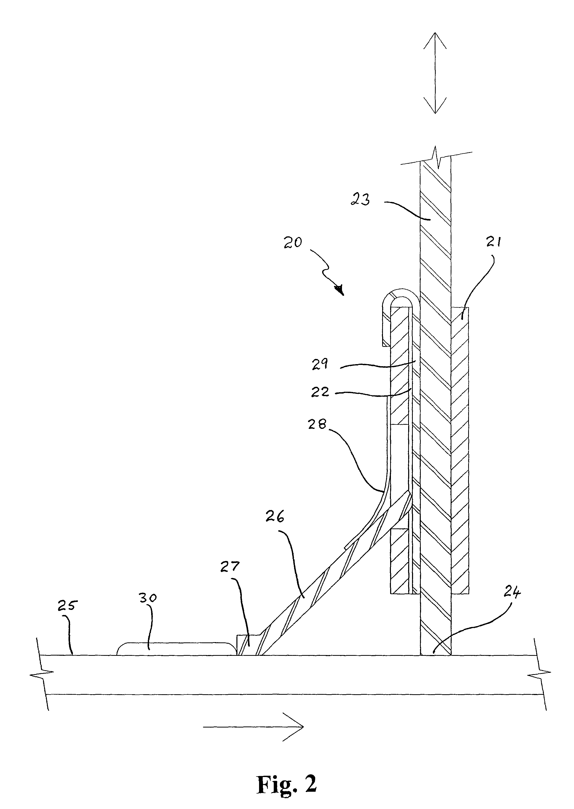
[0039]FIG. 2 illustrates a modified belt plough assembly according to the invention. The plough assembly 20 of FIG. 2 is similar to that of FIG. 1, in that it comprises a housing 21 having a slot 22 in which a blade 23 is slideably mounted in an upright orientation. The blade 23 has a lower edge portion 24 which rests upon the moving belt 25, and is free to move up and down to follow undulations in the belt.

[0040]The belt plough assembly 20 also has a link arm 26 extending obliquely downwardly from the housing 21 and in the counter direction to the direction of travel of the belt 25, i.e. on the upstream side of the blade 23. The link arm 26 is provided with a flat-bottomed foot portion 27 which rests upon the belt 25. The link arm 26 is connected to the housing 22 by a flexible strap 28 or other suitable hinge, so that the foot 27 of the link arm can ‘float’ on the surface of the belt 25.

[0041]A sheet of high friction material 29 is interposed between the upstream end of the blade ...

third embodiment

[0044]FIG. 3 illustrates the plough assembly in which a blade 33 is pivotally connected to a support 31 by a pivot arm 32. The support 31 may be part of the conveyor supporting framework. The pivot arm 32 is of relatively lightweight construction. The bottom edge 34 of the blade 33 rests on the belt 35. The blade 33 is able to pivot freely about its pivot connection to the support 31 so that it rests substantially under its own weight on the belt, and can maintain contact with the belt and follow any undulations in the moving belt. A damping mechanism as described above may be added to blade 33 or pivot arm 32.

[0045]As with the previous embodiments, the belt plough of FIG. 3 can use a blade of “ordinary” plastic / rubber which can operate primarily under its own weight without excessive wear rates or melting, and still provide a satisfactory cleaning performance.


PUM


Abstract

A belt plough assembly is used to deflect material on a conveyor belt. The belt plough assembly includes a support structure, and a blade operatively positioned by the support structure on the material carrying side of the conveyor belt and orientated to deflect or redirect outlying material on a conveyor belt back inside the alignment of the skirts. The support structure includes a housing having an upright slot within which the blade is slidably mounted. The blade rests on the belt under its own weight, but is freely movable relative to the support structure. This enables the blade to maintain contact with the belt and follow any undulations in the belt, and self-adjust for wear on the blade. A damper may be provided for damping movements of the blade.

Description

RELATED APPLICATIONS[0001]This application is the National Stage of International Application No. PCT / AU2011 / 000272, filed Mar. 10, 2011, entitled IMPROVED BELT PLOUGH, which claims the benefit of Australian Application No. 2010901000, filed Mar. 10, 2010, each of which is hereby incorporated by reference in their entirety.FIELD OF THE INVENTION[0002]This invention relates generally to bulk materials handling, and more specifically, it is directed to an improved belt plough for a belt conveyor.BACKGROUND ART[0003]A conveyor belt is typically used to convey bulk material from one or more upstream loading points to a downstream discharge location. The material is normally dropped onto the moving belt at each loading point, either vertically or at an angle.[0004]Skirting is used to contain the material while it settles down on the belt after loading. The skirting typically comprises upright barriers extending parallel to the longitudinal sides of the belt, a nominal distance in from th...

Claims


Application Information

Patent Timeline
Patent Type & Authority Patents(United States)
IPC IPC(8): B65G21/20B65G45/00
CPCB65G47/763B65G21/2081
Inventor SUNDSTROM, PAUL
Owner TASMAN WARAJAY
Why Eureka
Try Eureka