
Tissue marking implant

a technology of tissue marking and implants, which is applied in the field of implantable breast prostheses, can solve the problems of large scarring, large scarring, and large excised tissue in biopsies, and achieve the effect of reducing scarring and reducing excised tissu

Inactive Publication Date: 2014-03-11
SENORX
View PDF522 Cites 31 Cited by
  • Summary
  • Abstract
  • Description
  • Claims
  • Application Information

AI Technical Summary

Benefits of technology

The present invention provides an implant made of a resorbable material that can be used to reduce excised tissue and provide a support structure for the surrounding tissue. The implant is porous to allow for the growth of fibrous replacement tissue that does not encapsulate the implant and results in less scarring.

Problems solved by technology

Similarly, biopsies can leave small dimples or imperfections if remedial steps are not taken.
These methods have been complicated post-operatively by encapsulation of the implants, which can occur to varying degrees.
Encapsulation produces a hard area of scar tissue around the implant, resulting in a rigid, abnormally-shaped mount beneath the breast tissue or pectoralis muscle, depending upon the placement of the implant.
Moreover, the known implant materials may not be indicated for replacement of smaller amounts of tissue, as would be required to prevent dimpling after biopsies, for example.
Further, the known implant materials are not amenable to resizing.
In addition, known implants are not capable of being implanted through a cannula or needle, and are not readily instilled with medicaments or chemical agents that would be useful in treating the patient.

Method used


Image

  • Tissue marking implant
  • Tissue marking implant

Examples


Embodiment Construction

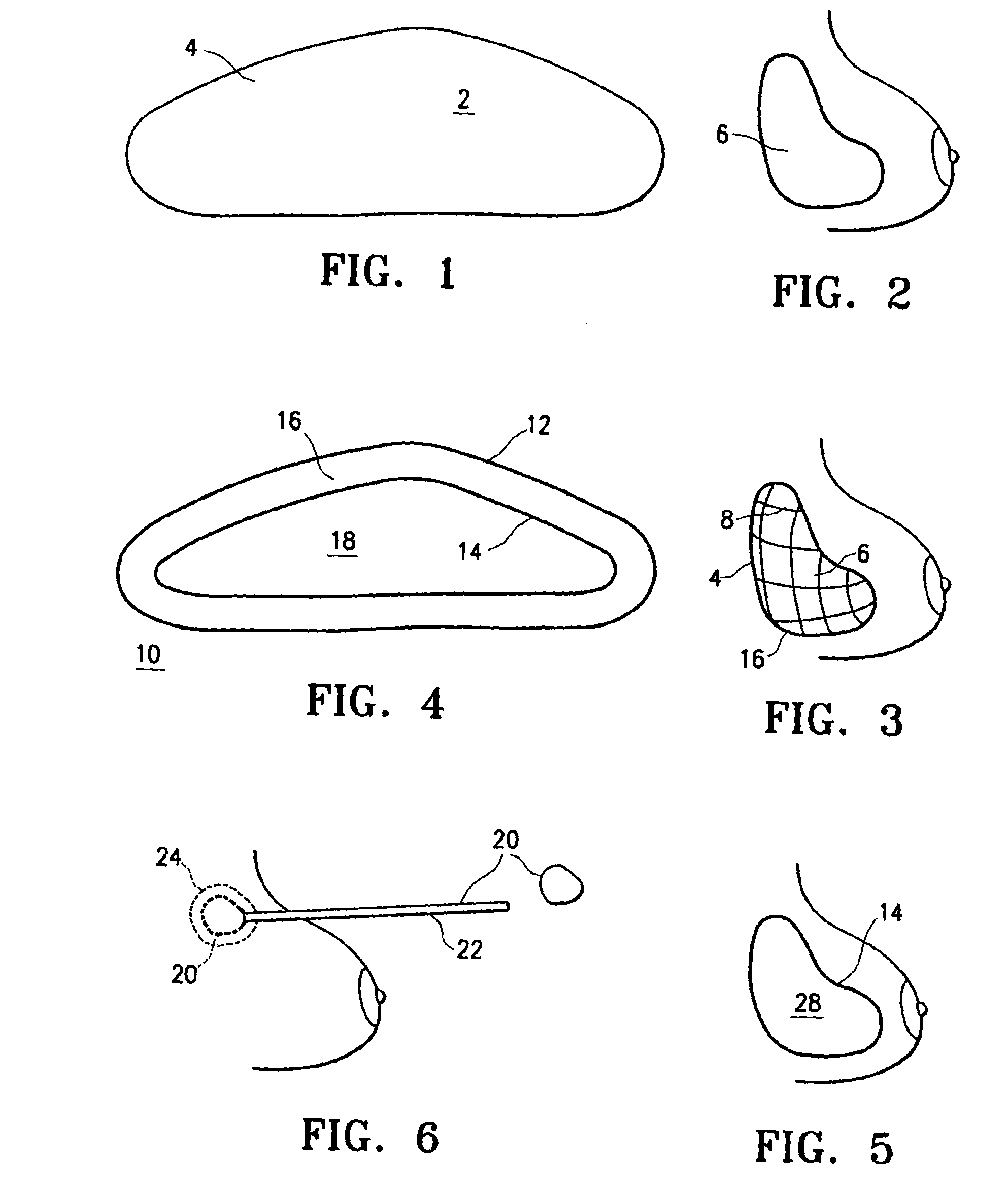
[0022]Referring initially to FIGS. 1 and 2, an implant 2 has an outer shell 4 made of a biosorbable material woven into a mesh. The inner contents of the implant are fluids such as saline and autologous blood products.

[0023]Outer shell 4 is made entirely of biosorbable materials, such as collagens or polyglycolic acids, for example. Over a period of approximately three weeks to six months, the outer shell dissolves, leaving the inner contents 6 present inside the breast. Hard encapsulation will not occur because there is not a foreign body contained within the prosthetic space.

[0024]Referring to FIG. 3, implantation of an alternative embodiment of implant 2 is illustrated in which the outer shell 4 includes both biosorbable material, and nonabsorbable material, such as monofilament polypropylene fibers. Outer shell 4 is provided as a mesh or weave of the mixed material, surrounding contents 6 as described above. After a resorption period, contents 6 remain surrounded by a skeletal o...


PUM

PropertyMeasurementUnit
sizeaaaaaaaaaa
structureaaaaaaaaaa
volumeaaaaaaaaaa

Abstract

An implant for marking an area within a living body includes a matrix material and a marking material. The implant is formable to fit the shape and size of a cavity in the human body. The implant is configured to support tissue surrounding the cavity and to allow in-growth of fibrous tissue into and replace at least a portion of the matrix material.

Description

CROSS REFERENCE TO RELATED APPLICATIONS[0001]This application is a continuation of application Ser. No. 12 / 965,405, filed Dec. 10, 2010, now U.S. Pat. No. 8,157,862, which is a continuation of application Ser. No. 12 / 589,413, filed Oct. 23, 2009, now U.S. Pat. No. 7,871,438, which is a divisional of application Ser. No. 11 / 108,785, filed Apr. 19, 2005, now U.S. Pat. No. 7,637,948, which is a continuation-in-part of U.S. patent application Ser. No. 10 / 627,718, filed Jul. 28, 2003, now U.S. Pat. No. 6,881,226, which is a division of application Ser. No. 09 / 828,806, filed Apr. 10, 2001, now U.S. Pat. No. 6,638,308, which is a continuation in part of U.S. patent application Ser. No. 09 / 169,351, filed Oct. 9, 1998, now U.S. Pat. No. 6,214,045, which claims the benefit of U.S. Provisional Application Ser. No. 60 / 061,588, filed Oct. 10, 1997, U.S. Provisional Application Ser. No. 60 / 077,639, filed Mar. 11, 1998, and U.S. Provisional Application Ser. No. 60 / 091,306, filed Jun. 30, 1998, the...

Claims


Application Information

Patent Timeline
Patent Type & Authority Patents(United States)
IPC IPC(8): A61F2/00A61F2/12A61L27/56A61L27/18A61L27/58
CPCA61F2/12A61L27/58A61L27/56A61B2019/5408A61L27/18A61F2/0077A61F2/0059A61B2090/3908A61F2210/0004A61F2210/0066A61L27/36
Inventor CORBITT, JR., JOHN, D.
Owner SENORX
Learn More