
Electrophotographic electrically conductive member

a technology of electrical conductivity and electrophotography, which is applied in the direction of corona discharge, shaft and bearing, thin material processing, etc., can solve the problems of white or black blotches, the increase of the number of electrophotographic images to be output, and the unevenness of the density produced in an electrophotographic image stripped. , to achieve the effect of suppressing the unevenness of electric resistance, increasing the number of electrophotographic images to be output, and increasing the local unevenness of the electric resistan

Active Publication Date: 2014-03-11
CANON KK
View PDF16 Cites 29 Cited by
  • Summary
  • Abstract
  • Description
  • Claims
  • Application Information

AI Technical Summary

Benefits of technology

[0008]As described above, as the conductive agent contained in the electrically conductive layer, the ion conductive agent has advantages over the electrically conductive agent for suppressing the unevenness of electric resistance of the charging member. However, even if the charging roller includes an electrically conductive layer having conductivity given using the ion conductive agent, it may cause the defects above attributed to local unevenness of discharge in the electrophotographic image. Particularly, when the number of the electrophotographic image to be output is increased because of a long-term use of the apparatus or when an image is formed under a low temperature and low humidity environment, the defects produced in an image attributed to the local unevenness of the electric resistance of the charging member are more likely to be increased.Further, the ion conductive agent may bleed to the surface of the charging roller, and it may adhere to the surface of the electrophotographic photosensitive member which is contacting with the charging roller.
[0009]The present invention is directed to providing an electrophotographic electrically conductive member in which conductivity needed for a charging roller can be secured, bleeding of an ion conductive agent can be suppressed, and defects in an image attributed to local unevenness of discharge can be reduced.

Problems solved by technology

A charging member having locally uneven electric resistance may cause a photosensitive member to be locally unevenly discharged, leading to white or black blotches or a stripped unevenness of a density produced in an electrophotographic image.
However, even if the charging roller includes an electrically conductive layer having conductivity given using the ion conductive agent, it may cause the defects above attributed to local unevenness of discharge in the electrophotographic image.
Particularly, when the number of the electrophotographic image to be output is increased because of a long-term use of the apparatus or when an image is formed under a low temperature and low humidity environment, the defects produced in an image attributed to the local unevenness of the electric resistance of the charging member are more likely to be increased.
Further, the ion conductive agent may bleed to the surface of the charging roller, and it may adhere to the surface of the electrophotographic photosensitive member which is contacting with the charging roller.

Method used


Image

  • Electrophotographic electrically conductive member
  • Electrophotographic electrically conductive member
  • Electrophotographic electrically conductive member

Examples


example 1

Production of Charging Roller No. 1

[0099]The elastic roller No. 1 was dipped once in the coating solution No. 1 prepared above to form a coating film of the coating solution No. 1 on the surface of the elastic layer. The time for dipping coating was 9 seconds, and a dipping coating pulling rate was adjusted such that an initial rate was 20 mm / sec and the final rate was 2 mm / sec. The rate was linearly changed with time between 20 mm / sec and 2 mm / sec.

[0100]Subsequently, the elastic roller 1 having the coating film formed on the surface thereof was left as it was in an environment at a temperature of 25° C. for 30 minutes. Next, the elastic roller 1 was placed for 1 hour in a hot air circulating dryer set at a temperature of 90° C. Further, the elastic roller 1 was placed for 1 hour in the hot air circulating dryer set at a temperature of 160° C. to react the coating film. Thus, a surface layer as the electrically conductive layer was formed on the elastic layer. Thus, the charging rol...

examples 2 to 42

[0114]Charging rollers Nos. 2 to 42 were produced in the same manner as in the charging roller No. 1 except that coating solutions having a number shown in Table 10 were used for formation of the electrically conductive layer as the surface layer. These charging rollers were evaluated in the same manner as in the charging roller No. 1.

[0115]

TABLE 10Evaluation 1Environ-mentalVolume resistivityfluctuationEvaluation of imageN / NL / Ldigit ofEvaluationEvaluationCoatingEnviron-Environ-volumeEvaluationEvaluation45Examplesolution No.mentmentresistivity23(kV)(%)111.1E+073.4E+081.49AC1.4498228.1E+061.9E+081.37AC1.4598336.3E+062.5E+070.61AA1.4698444.1E+062.4E+070.76AB1.5398558.6E+063.9E+070.65AA1.4898665.5E+062.1E+070.58AA1.5298774.6E+061.8E+070.59BA1.5798886.6E+062.9E+070.65AA1.4599998.4E+063.2E+080.58AA1.419810108.1E+062.6E+070.51AA1.399911115.9E+063.2E+070.74AA1.488312125.5E+064.1E+070.87AB1.596413137.0E+064.5E+070.81AB1.576614146.1E+063.2E+070.72AA1.468915157.1E+064.0E+070.74AB1.558716166.8E...

examples 43 to 53

[0116]Charging rollers Nos. 43 to 53 were produced in the same manner as in charging roller No. 1 except that the elastic roller No. 1 was replaced by the elastic roller No. 2 and the surface layer was formed using coating solutions having a number shown in Table 11, and were subjected to Evaluation 1 to Evaluation 5. The results are also shown in Table 11.

[0117]

TABLE 11Evaluation 1Environ-Volume resistivitymental(Ω· cm)fluctuationEvaluation of imageCoatingN / NL / Ldigit ofEvaluationEvaluationsolutionEnviron-Environ- volumeEvaluationEvaluation45ExampleNo.mentmentresistivity23(kV)(%)4312.9E+078.5E+081.46AC1.45994432.2E+074.4E+070.30AB1.52994541.7E+074.1E+070.38AB1.589946102.5E+074.6E+070.27AB1.379947142.4E+075.3E+070.35AB1.439148152.4E+075.7E+070.37AB1.58749224.6E+071.7E+091.57AC1.419950232.9E+077.4E+070.40AB1.389951253.3E+077.6E+070.36AB1.339952293.1E+078.1E+070.42AB1.49053303.2E+079.0E+070.45AB1.5289


PUM


Abstract

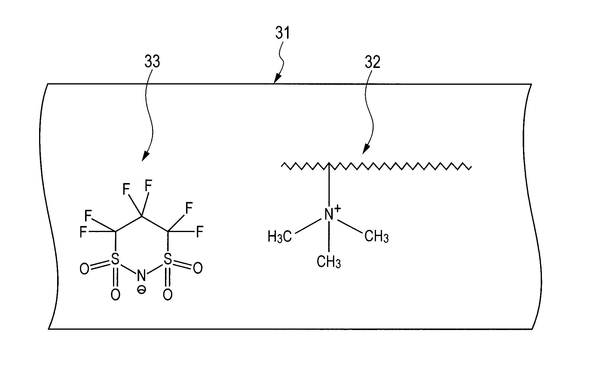
The present invention provides an electrophotographic electrically conductive member in which conductivity needed for a charging member is secured, and defects in an image attributed to uneven discharging can be minimized independently of a long-term use and an environment of use. An electrophotographic electrically conductive member comprising an electrically conductive support and an electrically conductive layer, wherein the electrically conductive layer includes an ion conductive resin having a quaternary ammonium ion in a molecule structure as a binder resin, and a carrier molecule represented by the following formula (1) or (2):(wherein n1 and n2 each independently represent an integer of 1 to 4).

Description

CROSS-REFERENCE TO RELATED APPLICATIONS[0001]This application is a continuation of International Application No. PCT / JP2012 / 001851, filed Mar. 16, 2012, which claims the benefit of Japanese Patent Application No. 2011-062717 filed Mar. 22, 2011 and Japanese Patent Application No. 2012-051718 filed Mar. 8, 2012.BACKGROUND OF THE INVENTION[0002]1. Field of the Invention[0003]The present invention relates to an electrophotographic electrically conductive member used for electrophotographic apparatuses and process cartridges.[0004]2. Description of the Related Art[0005]In image forming apparatuses using an electrophotographic method, namely, electrophotographic apparatuses, electrically conductive members are used in various applications, i.e., as members such as a charging member, a developing member, and a transfer member. In the electrophotographic apparatus, a charging roller as a charging member is disposed in contact with an electrophotographic photosensitive member to charge the ...

Claims


Application Information

Patent Timeline
Patent Type & Authority Patents(United States)
IPC IPC(8): G03G15/02
CPCF16C13/00G03G15/0233G03G15/0818G03G15/1685Y10T428/31504
Inventor YAMAUCHI, KAZUHIROMURANAKA, NORIFUMINISHIOKA, SATORUKIKUCHI, YUICHI
Owner CANON KK
Learn More