Micro motor locking system

a technology of locking system and micro-motor, which is applied in the direction of electric permutation locks, non-mechanical controls, and applications of locking or unlocking, etc., can solve the problems of excessive power consumption of the bobbin during locking or unlocking, excessive consumption of the bobbin, and burning of the driving centr

Active Publication Date: 2014-03-18
VEMUS ENDUSTRIYEL ELEKTRONIK SANAYI & TICARET SIRKETI
View PDF32 Cites 32 Cited by
  • Summary
  • Abstract
  • Description
  • Claims
  • Application Information

AI Technical Summary

Benefits of technology

[0013]Another purpose of the invention is to provide smaller sizes and decrease number of parts to reduce cost and thus provide a locking system of good aesthetic appearance.
[0015]Another purpose of the invention is to provide a long life locking system by means of preventing burning of driving center.
[0017]A further purpose of the invention is to provide cost decrease by means of electronic locking system.
[0020]In order to realize all the advantages mentioned above and to be better understood from the detailed description provided below, the invention is to develop a micro motor locking system, comprising a locking bolt mounted inside a lock in order to provide locking of electronic gates, drawers, cabinet, safe and similar ones, the locking bolt having a locking position by entering into a lock housing structured on the lock and an unlocking position by removing from the lock housing; a motor providing a driving force for the locking bolt to enter into the lock housing and remove from the lock housing; a worm gear performing rotational motion around its own axis by means of the driving force from the motor; and members transferring the rotational motion of the worm gear to the locking bolt by transforming the rotational motion into a linear motion of the locking bolt, needing lower power requirement, ensuring lower cost due to less number of parts and small sites, capable to operate at lower voltages and providing secure locking distance.

Problems solved by technology

Such bobbins consume too much power during locking or unlocking.
And this causes burning of driving centre.
In the known related art, too much power is consumed for the voltage and ampere values in locking systems and this causes short operating life of electronic locking systems.
However, in such systems lock bolts can leave the housing easily, that is, the locking distance is considerably short.
This can cause removal of the lock from the housing with a small stroke.
In the related art, the sizes of electronic locking systems are too big and number of parts is too many, which causes increase in cost of production and problem in aesthetics.
In the related art, electronic locking systems are not secure due to the reasons given above, which cause risk on life of people and problems in safety.

Method used


Image

  • Micro motor locking system
  • Micro motor locking system
  • Micro motor locking system

Examples


Embodiment Construction

[0062]In this detailed description of the invention, the preferred embodiments of the micro motor locking system (8) being subject of this invention have been described only for the purpose of better understanding of the subject without any restrictive effects.

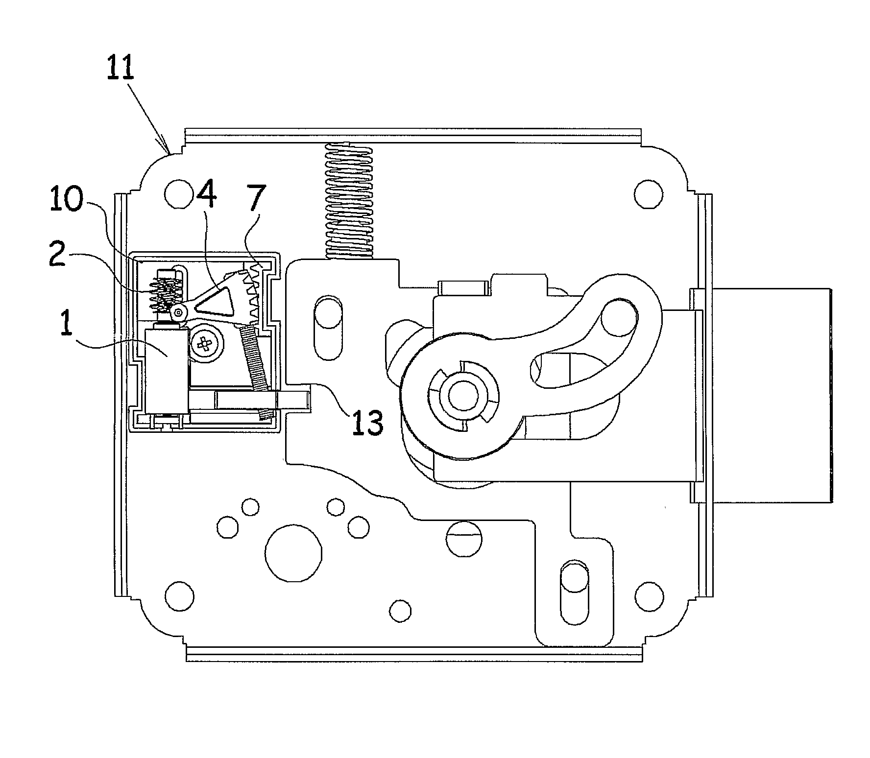
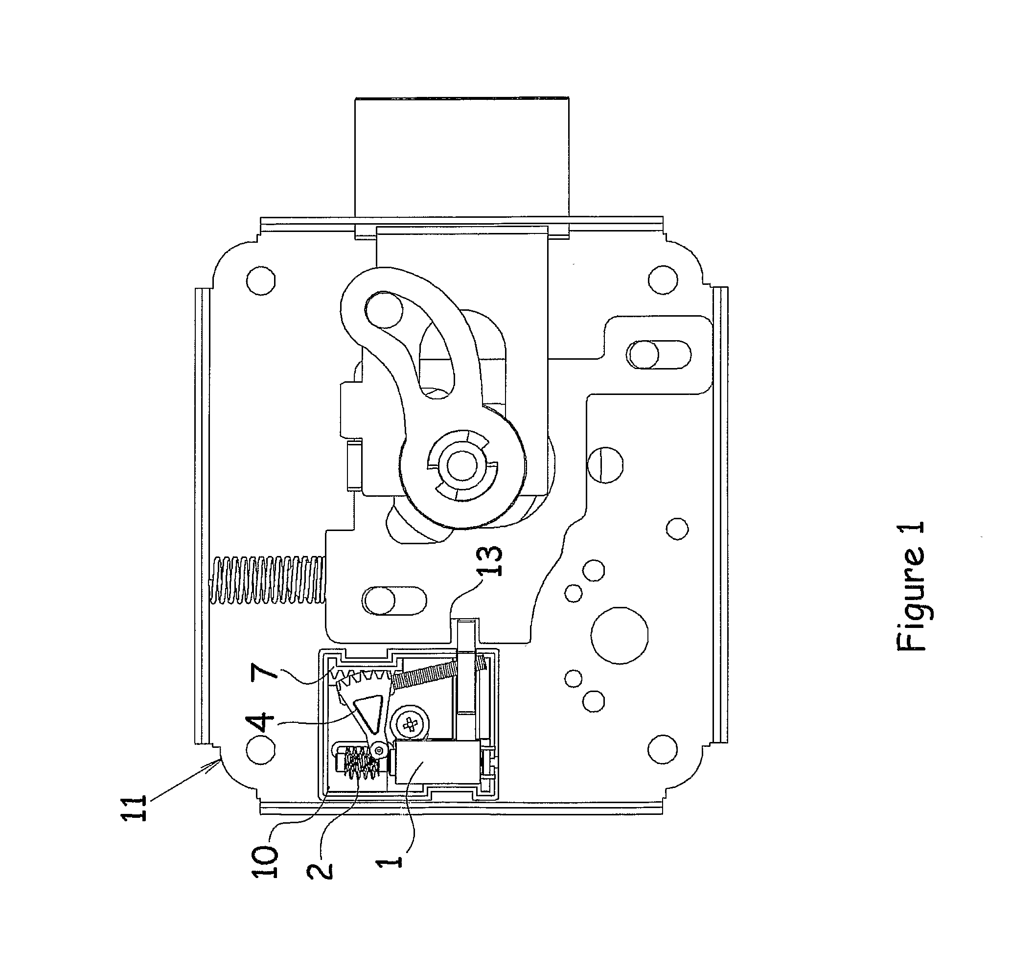
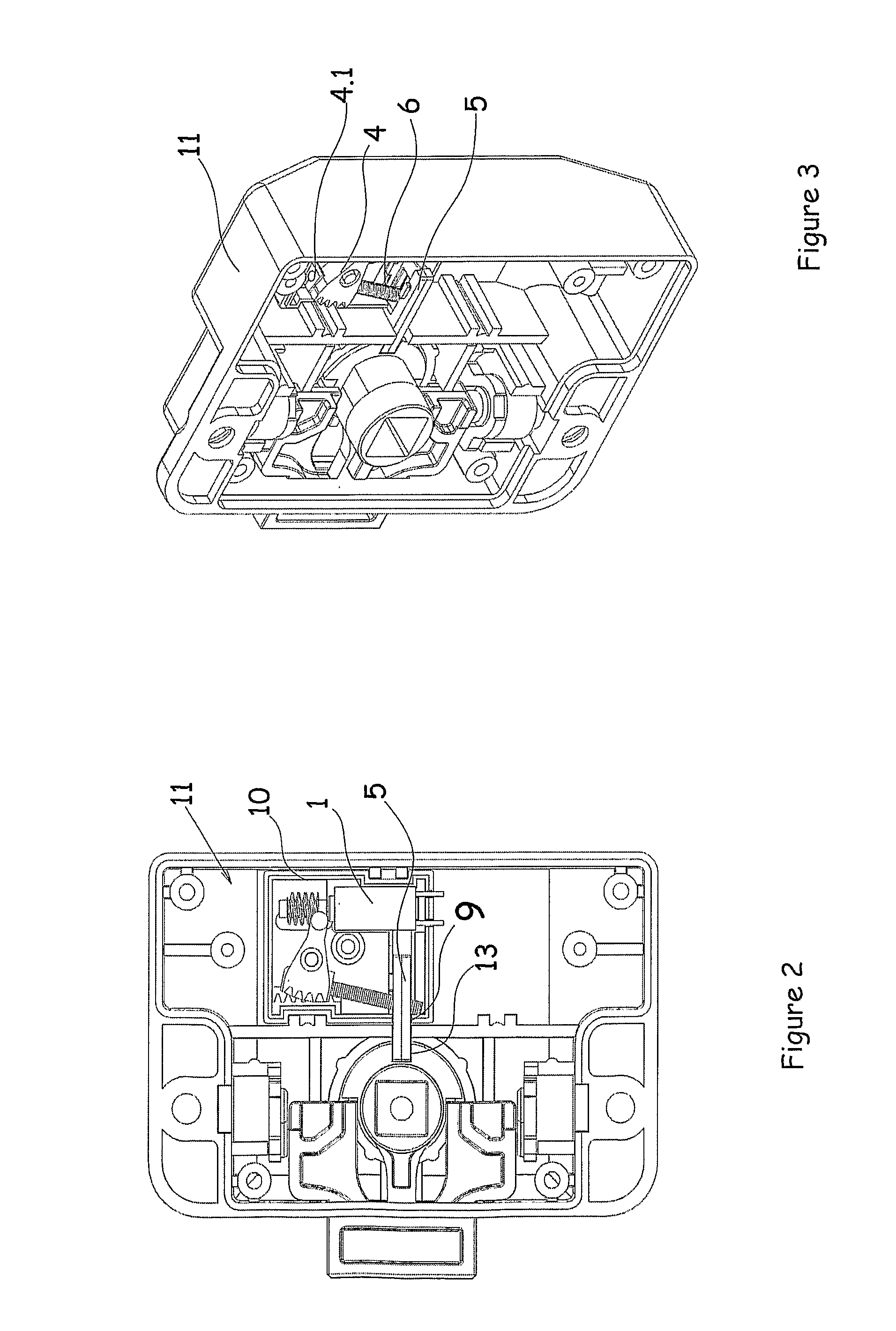
[0063]The lock (11) samples in which a micro motor locking bolt system (8) according to the invention is used are shown in FIGS. 1, 2, 3 and 4. Based on this, the purpose of the invention is to enable locking process in such a manner that the locking bolt (5) connected to the micro motor locking bolt system (8) enters into the lock housing (13) structured on the lock (11). The micro motor locking bolt system (8) is mounted into a support body (10). A body housing (9) is structured at the same direction with the said lock housing (13) on the support body (10). Thanks to this body housing (9), the locking bolt (5) enters into and removes from the lock housing (13). In order to check if the locking process is performed or not, se...


PUM


Abstract

A micro motor locking bolt system (8) comprising a locking bolt (5) mounted inside a lock (11) in order to provide a locking function in electronic gates, drawers, cabinets, safes and similar structures. The locking bolt system has a locking position by entering into a lock housing (13) structured on the lock (11) and an unlocking position by removing from the lock housing (13). A motor (1) provides the necessary driving force in order for the locking bolt (5) to enter into and be removed from the lock housing (13). A worm gear (2) performs rotational motion around its own axis due to the driving force from the motor (1) and comprises grooved parts (2.1) thereon. Motion transmission members transfer the rotational motion of the worm gear (2) to the locking bolt (5) by transforming the rotational motion into linear motion.

Description

THE RELATED ART[0001]The invention relates to micro motor locking systems comprising a locking bolt mounted inside a lock in order to provide locking of electronic gates, drawers, cabinet, safe and similar structures, the locking bolt having a locking position by entering into a lock housing structured on the lock and an unlocking position by removing from the lock housing; a motor providing a driving force for the locking bolt to enter into the lock housing and remove from the lock housing; a worm gear performing rotational motion around its own axis by means of the driving force from the motor; and members transferring the rotational motion of the worm gear to the locking bolt by transforming the rotational motion into at linear motion of the locking bolt.BACKGROUND OF THE RELATED ART[0002]Today it is known that embodiments such as electronic gates, drawers, cabinets, safe and similar structures are used for controlled passing systems. In such types of locking systems, the user en...

Claims


Application Information

Patent Timeline
Patent Type & Authority Patents(United States)
IPC IPC(8): E05B47/06
CPCE05B2047/0021E05B2047/0016E05B47/0603E05B2047/0031E05B2015/0496E05B2015/0472E05B2015/0403E05B47/0673E05B2047/0093E05B47/0012Y10T70/713Y10T70/7102Y10T70/7062Y10T70/7113
Inventor DAYANIKLI, VEHBIDAYANIKLI, MUSTAFA
Owner VEMUS ENDUSTRIYEL ELEKTRONIK SANAYI & TICARET SIRKETI
Why Eureka
Try Eureka