
Cascade impactor

a cascade impactor and cascade technology, applied in the field of aerosol particle sampling, can solve the problems of large collection surface, non-ideal calibration, and operating conditions outside the ideal range, and achieve the effect of less coating material and improved collection efficiency of cascade impactor stages

Inactive Publication Date: 2014-03-18
WITHAM CLYDE L
View PDF15 Cites 2 Cited by
  • Summary
  • Abstract
  • Description
  • Claims
  • Application Information

AI Technical Summary

Benefits of technology

[0007]Additional advantages of some embodiments of the invention include a reduced number of orifices compared to other cascade impactors, thus eliminating the inaccuracies due to many small holes. Another advantage of some embodiments includes the use of relatively large orifice diameters compared to currently available cascade impactors. The larger orifices allow for much easier removal of the particulate matter that may be lost in and around the orifices for analysis.
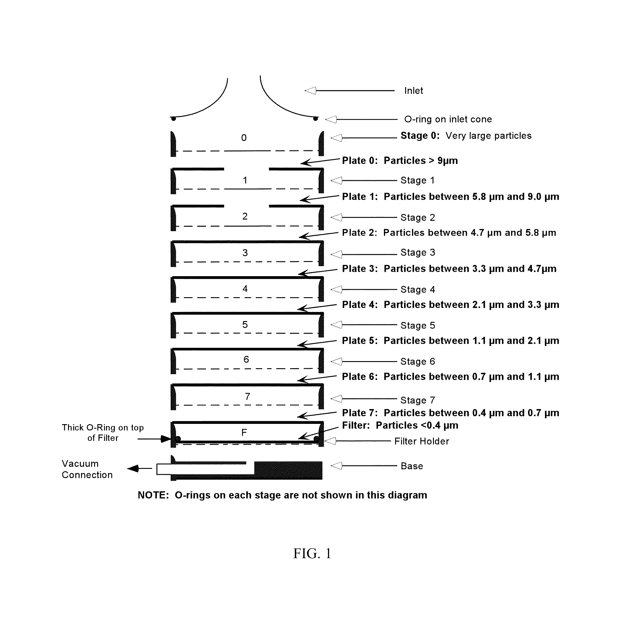
[0035]To improve the collection efficiency of cascade impactor stages and avoid bouncing of particles after impacting on the collecting surfaces, it is known that a coating material should be applied to the collection surfaces. Most methods involve spraying or dipping of collection plates (such as those shown schematically in FIG. 1) with a silicone or other coating material that will retain the particles on the surface following impaction. An apparatus and method described herein allows coating of the collection surfaces directly opposing the orifices after the impactor is assembled and ready for use. The method results in less coating material being applied and application only to the areas where it is needed. Using less coating material reduces the chances that it will interfere with the analytical methods for the pharmaceutical or test aerosol.

Problems solved by technology

At these high flow rates, numerous orifices must be used on each stage, resulting in operating conditions outside of the ideal range, and consequently non-ideal calibrations.
Further, these devices have large collection surfaces requiring the collection of relatively large amounts of material to satisfy analytical method requirements.
Their size also creates inaccuracies in measurement due to interstage losses of material unaccounted for in routine analysis (Marple V A, Willeke K. Inertial impactors: theory, design, and use.
Further, these devices are not well suited for sampling aerosols intended for delivery to infants and children.
If not, the particles can bounce or be blown off or be re-entrained by the airflow, thus rendering the analysis of particle size erroneous.
Typically, the entire collection plate is coated by either dipping or spray or eyedropper application, and this can result in additional error for both gravimetric and quantitative chemical analysis, due to extraneous materials on the plate.

Method used


Image

  • Cascade impactor
  • Cascade impactor
  • Cascade impactor

Examples


example 1

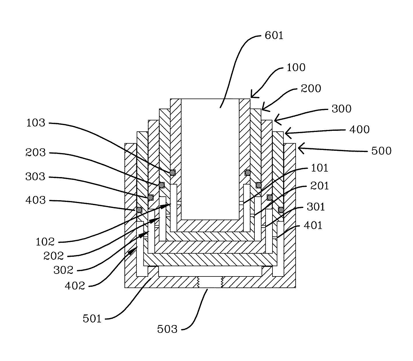
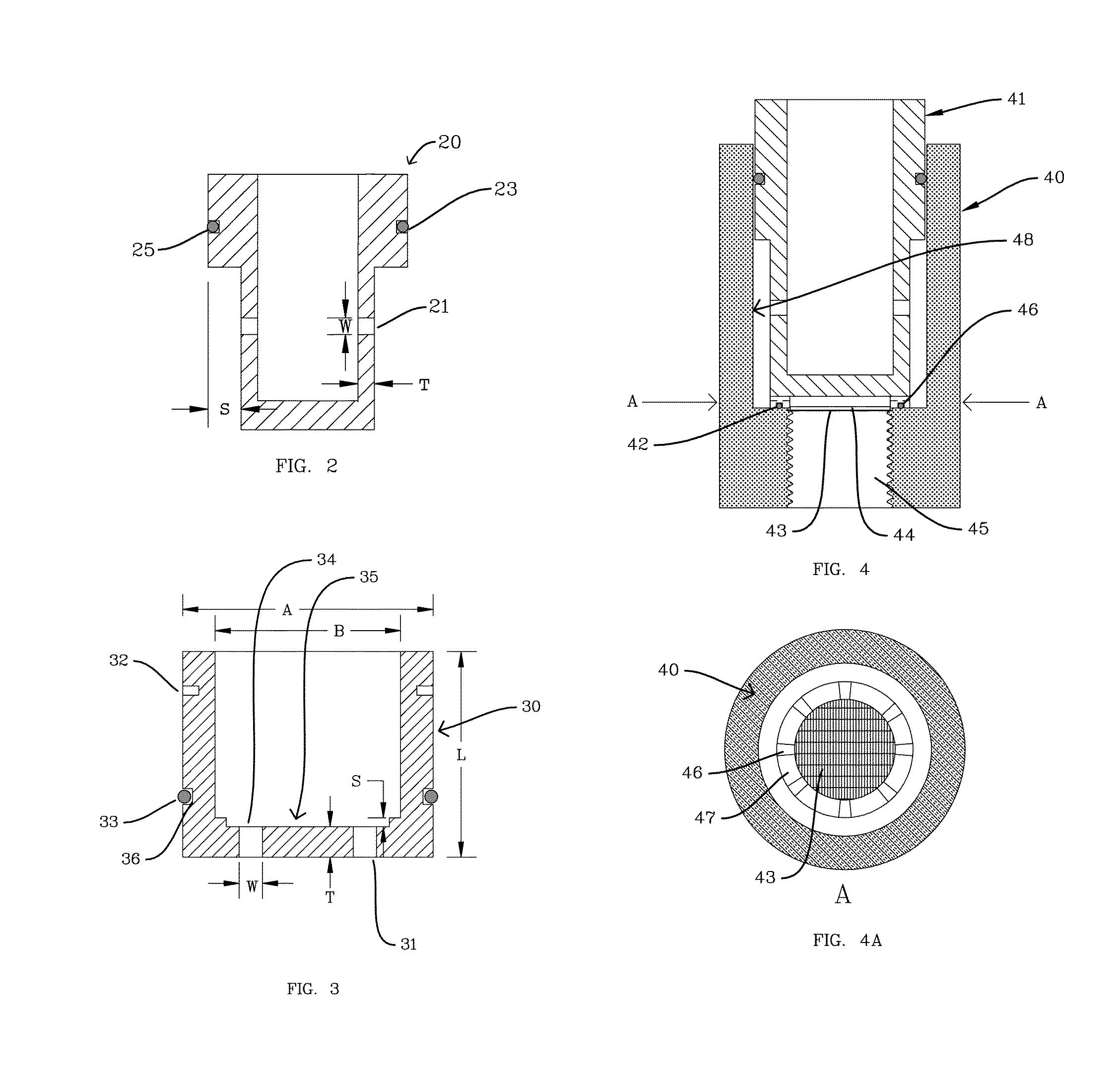
[0204]A cascade impactor with 4 collection stages and a filter stage was constructed according to the embodiment depicted in FIG. 3 and FIG. 7 and described in Table 1. This particular embodiment was designed to operate at 4 liters per minute total air flow. For the example described herein, clear plastic disks, 3.5 mil thick, were placed on each stage at the points of particle impaction in the cascade impactor to serve as particle collection substrates and allow for subsequent microscopic evaluation of the collected particles.

[0205]

TABLE 1Dimensions of one embodiment of a cascade impactor as describedherein whereby one or more orifices are on the bottom surfaces of theimpactor stages. The dimensions arereferenced to FIG. 3.Cutoff SizeDimensions [inches]No.D50(C)1 / 2StageABLWTSOrifices[micrometers]10.500.3391.250.18500.1850—16.9520.750.501.1250.11300.11300.37024.7131.000.751.000.11300.11300.22613.3641.251.001.000.03900.03900.22611.02Filter1.501.251.50——0.078—A = Nominal Outer Diamete...

example 2

[0206]The apparatus of FIG. 9 was assembled. The container had a volume of about 475 ml and was pressurized to about 145 psig. A 1:100 dilution of silicone Antifoam (Dow Corning 1520) in water was added to a VixOne nebulizer (Westmed, Greenwood Village, Colo.). The valve was opened and an aerosol of the diluted silicone coating material was generated and sampled into the cascade impactor of Example 1 at a flow rate of 4 lpm. This method was repeated one more time, resulting in a total of 0.8 mg to 1.0 mg of coating material being deposited on the plastic disk collection surfaces of the impactor. The plastic disks described in Example 1 were removed and evaluated. The silicone was uniformly distributed (about 0.1 to 0.2 mg) on each collection substrate. Microscopic examination of the substrates indicated a much more uniform coating than when compared to conventional application by an eyedropper. The coating thickness was uniform and adequate for trapping particles, and the coated are...

example 3

[0207]The impactor of Example 1 was once again reassembled, with clean clear plastic disks as described in Example 1. To coat the collection substrate surfaces, an aerosol of silicone Antifoam diluted 1:100 in water was produced by the apparatus depicted in FIG. 9 and the method described in Example 2. The Antifoam coating aerosol was sampled by the cascade impactor for 15 seconds with a flow rate of 4 l / min. Immediately following this, 5.1 mg of a test aerosol comprising a dry powder formulation of placebo measles vaccine was aerosolized into a spacer (Aerochamber Max, Trudell Medical, London, Ontario, Canada) and sampled into the impactor with a flow rate of 4 lpm for 30 seconds.


PUM

PropertyMeasurementUnit
aerodynamic diameteraaaaaaaaaa

Abstract

The invention relates to low flow rate cascade impactors for sampling aerosols, notably but not limited to pharmaceutical aerosols. The impactor stages serve as both orifice plate and collecting cup, simplifying collection and analysis. The impactor is designed to operate at flow rates approximating the inspiratory flow rates of young children and infants. Also presented is a method of and apparatus for applying a coating material to the collection surface of the stages after an impactor is assembled for use. The method entails generation of a polydisperse aerosol and sampling into the impactor. The coating substance improves the trapping of particles on the stages. The apparatus and method of application limit the amount of coating material applied and confines it to the regions of particle impact opposite the stage orifices.

Description

CROSS-REFERENCE TO RELATED APPLICATIONS[0001]This application claims the benefit of U.S. Provisional Application No. 60 / 977,070 filed 2 Oct. 2007, and PCT / U.S.08 / 77769 filed 26 Sep. 2008 which are incorporated herein by reference.FIELD OF THE INVENTION[0002]The present invention relates to the field of aerosol particle sampling. In particular, the invention relates to cascade impactors for sampling pharmaceutical aerosol preparations at low flow rates.BACKGROUND OF THE INVENTION[0003]A cascade impactor is an aerosol-sampling device that samples and separates the aerosol according to the aerodynamic properties of the particles. The typical cascade impactor has multiple collection stages arranged in series, with each collection stage having an orifice plate and a separate, removable collection surface positioned below the orifices (FIG. 1). With each successive stage, the total cross-sectional area of all of the orifices decreases in order to increase the velocity of the particle-lade...

Claims


Application Information

Patent Timeline
Patent Type & Authority Patents(United States)
IPC IPC(8): G01N1/22
CPCG01N15/0255G01N2015/0261B01D50/002G01N1/2208B01D46/10B01D45/08B01D50/20
Inventor WITHAM, CLYDE, L.
Owner WITHAM CLYDE L
Learn More