Athletic shoe with heel counter for maintaining shape of heel section

a technology of heel section and heel counter, which is applied in the direction of uppers, bootlegs, stiffners, etc., can solve the problems that the heel counter disclosed in the above publications does not give any consideration as to the difference, and achieve the effect of suppressing the foot falling

Active Publication Date: 2014-03-25
ASICS CORP
View PDF22 Cites 34 Cited by
  • Summary
  • Abstract
  • Description
  • Claims
  • Application Information

AI Technical Summary

Benefits of technology

[0010]During a run, a foot lands starting from the outer side of the heel, and then the center of the load moves to the inner side of the front foot portion. The heel pronates in this process, and suppressing excessive pronation is useful in preventing foot injuries during running.

Problems solved by technology

However, the heel counters disclosed in the above publications fail to give any consideration as to the difference between pronation (heel eversion) and supination (heel inversion) of the heel.

Method used


Image

  • Athletic shoe with heel counter for maintaining shape of heel section
  • Athletic shoe with heel counter for maintaining shape of heel section
  • Athletic shoe with heel counter for maintaining shape of heel section

Examples


embodiment 1

[0071]

[0072]FIGS. 1 to 3, 4A, 5 and 6 show Embodiment 1.

[0073]General Configuration:

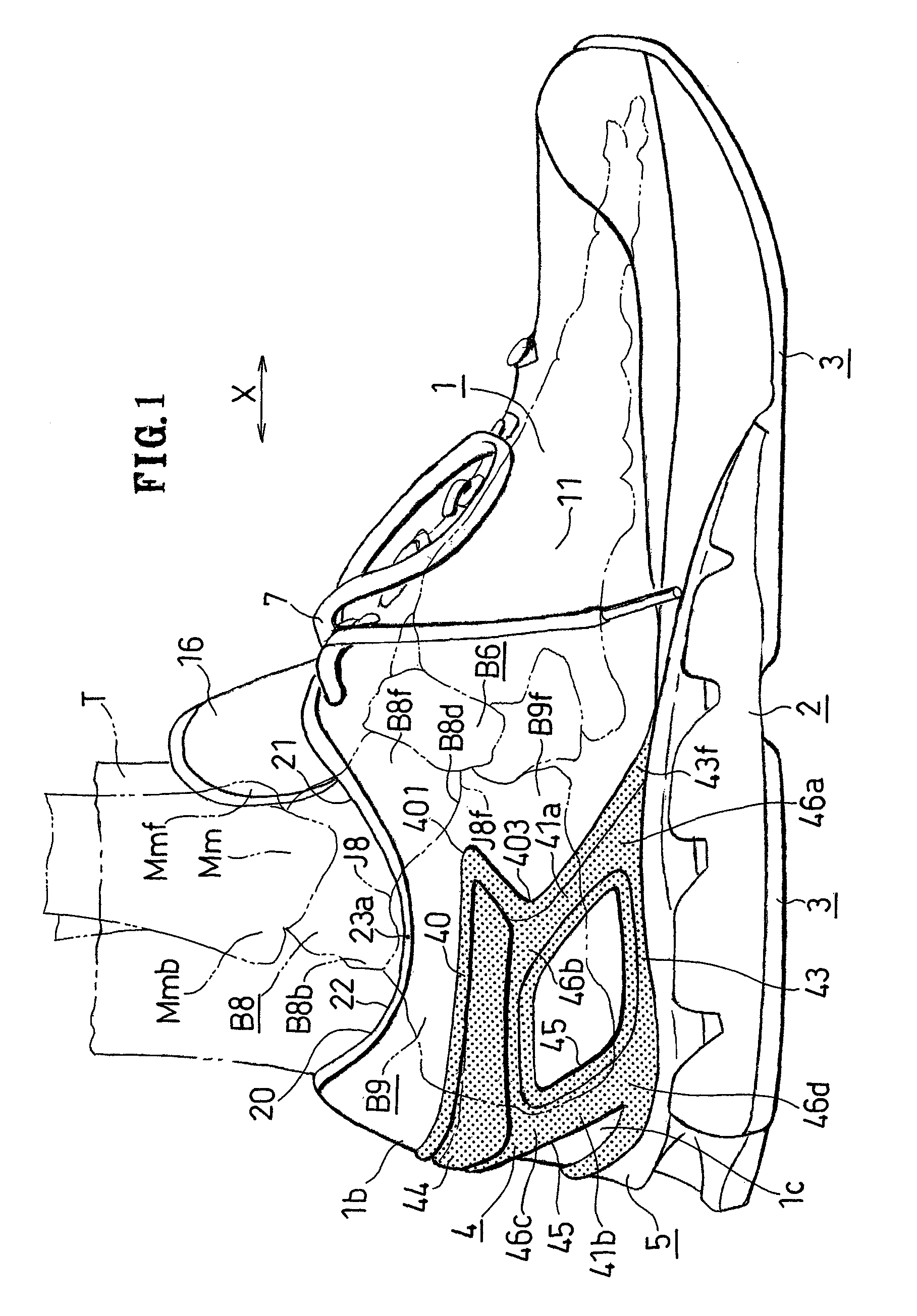
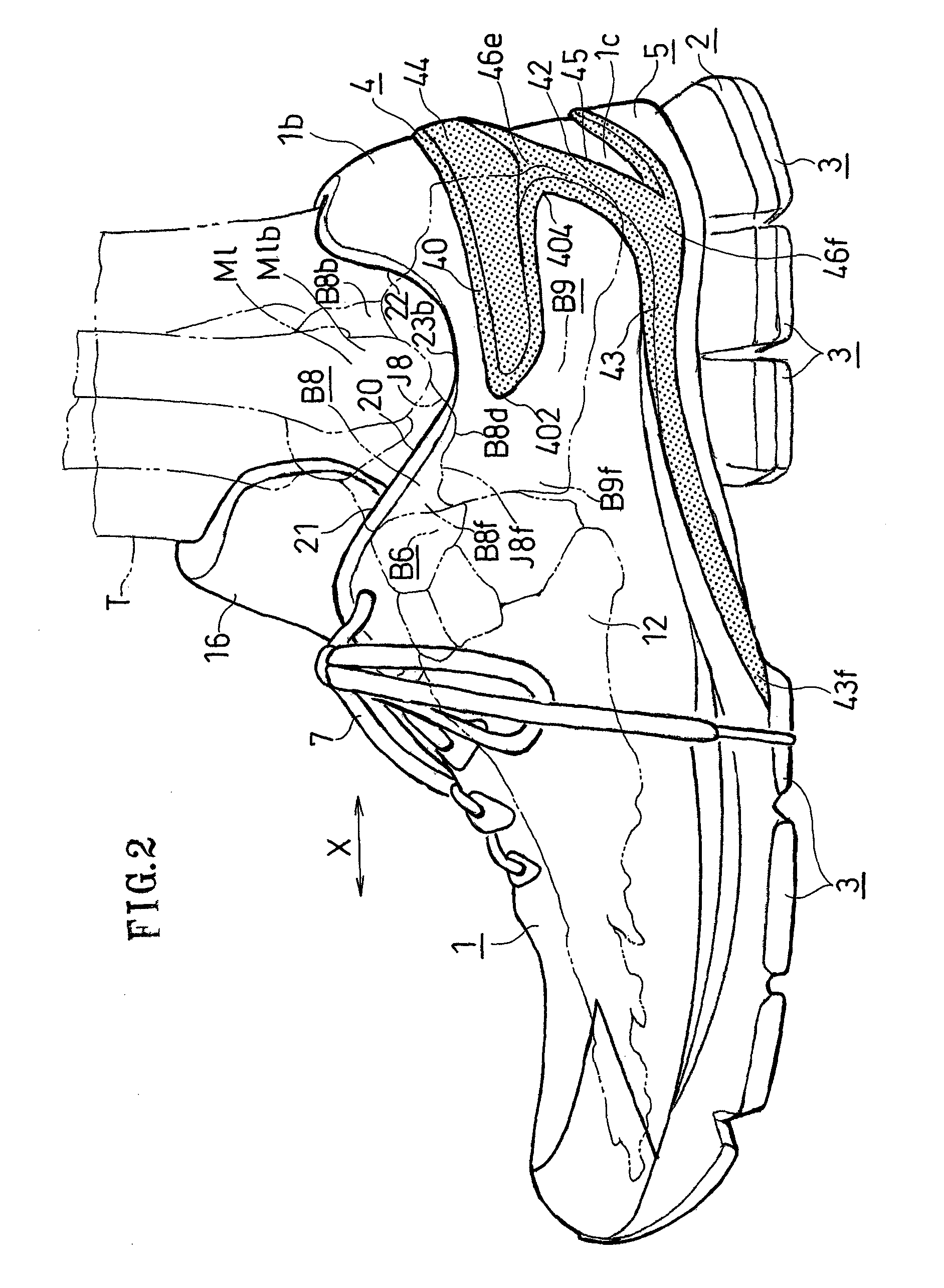
[0074]As shown in FIGS. 1 to 3, the present athletic shoe includes an upper 1, a midsole 2, an outsole 3, and a heel counter 4.

[0075]As shown in FIG. 4A, the upper 1 includes a cushion 15 made of a resin foam between a quarter 13 and a quarter lining 14. Note that the quarter 13 and the quarter lining 14 may each be formed by a plurality of layers of fabric.

[0076]An insole 6 is sewn onto the upper 1. On the other hand, as shown in FIG. 1, the upper 1 includes an opening (collar) 20 through which the leg T extends upward and through which the foot is inserted.

[0077]The upper 1 includes a fastening means (fastener) such as a shoelace 7, and the upper 1 is fastened by the shoelace 7 so that a medial side 11 of the upper 1 and a lateral side 12 of FIG. 2 are brought into close contact with the foot in the vicinity of the opening 20. Note that the reference numeral 16 denotes a tongue provided in front of...

embodiment 2

[0126]

[0127]FIG. 4B shows Embodiment 2.

[0128]As shown in FIG. 4B, the heel counter 4 is bonded to the medial side 11, the back side 1b and the lateral side 12 inside the upper 1. In this case, the heel counter 4 is bonded to the quarter 13. The rib 40 bonded to the quarter 13 increases the flexural rigidity of the upper 1.

[0129]Note that the midsole 2, the heel cup 5 and the outsole 3 of FIG. 1 are stacked together below the heel counter 4 and the insole 6.

embodiment 3

[0130]

[0131]FIGS. 7 to 10 show Embodiment 3.

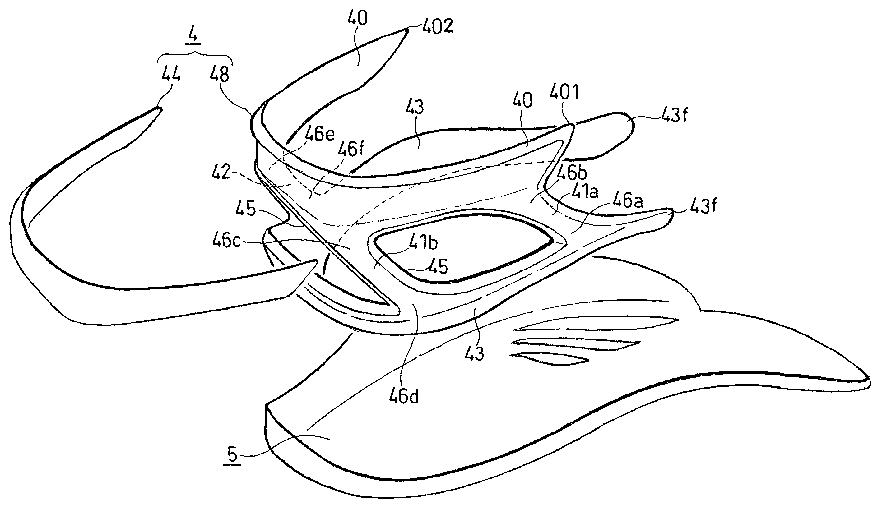
[0132]As shown in FIGS. 7 to 9, the heel counter 4 of Embodiment 3 includes the first and second bridges 41a and 42.

[0133]As shown in FIG. 7, on the medial side 11 of the upper 1, the front first bridge 41a is formed in a curved shape extending in a curved pattern from the front end 401 toward a position under the vicinity of the rear end portion of the calcaneal bone B9 (FIG. 1).

[0134]As shown in FIG. 9, the second bridge 42 is located at the center of the back side 1b of the upper 1.

[0135]Note that as shown in FIG. 10, the heel counter 4 is formed integral with the heel cup 5. The heel cup 5 supports the rear foot portion and the mid foot portion.


PUM

PropertyMeasurementUnit
shapeaaaaaaaaaa
distancesaaaaaaaaaa
rigidityaaaaaaaaaa

Abstract

A heel counter 4 includes: a support section 43 extending in a forward direction from a back side 1b of an upper 1; a rib 40 extending in the forward direction generally in parallel to the support section 43 at a position above the support section 43 from the back side 1b of the upper 1 along a medial side 11 and extending in the forward direction generally in parallel to the support section 43 at a position above the support section 43 from the back side 1b of the upper 1 along a lateral side 12; and first and second bridge means 41a, 41b and 42 connecting the support section 43 and the rib 40 to each other allowing the support section 43 to support the rib 40, wherein: a foremost one 46b of a plurality of connection portions 46b, 46c and 46e by which the rib 40 and the bridge means 41a, 41b and 42 are connected to each other is provided on the medial side of the upper 1; and the foremost connection portion 46b is located forward of a rear end of a talus bone B8.

Description

TECHNICAL FIELD[0001]The present invention relates to an athletic shoe with a heel counter for maintaining a shape of a heel section.BACKGROUND ART[0002]A heel counter covers the opposing side surfaces and the back surface of the heel and maintains the shape of the heel section of the upper. If the entire heel is wrapped by a heel counter formed by a resin part, the heel section of the upper has a high rigidity, but it inhibits the deformation of the upper in conformity to the shape of the heel of the wearer. In other words, it lowers the fit around the heel section.[0003]For example, a heel counter with a rib extending along the opening is known in the art as listed below.[0004][First Patent Document] Japanese Laid-Open Utility Model Publication No. S52-104454 (FIG. 2)[0005][Second Patent Document] Japanese Laid-Open Utility Model Publication No. H02-061202 (FIG. 5)[0006][Third Patent Document] Japanese Laid-Open Patent Publication No. S64-008904 (FIG. 11)[0007][Fourth Patent Docum...

Claims


Application Information

Patent Timeline
Patent Type & Authority Patents(United States)
IPC IPC(8): A43B23/08
CPCA43B7/20A43B7/16A43B23/088A43B23/17
Inventor NISHIWAKI, TSUYOSHIMORIYASU, KENTANAKAYA, SEIGOKUROSAKI, KIYOMITSU
Owner ASICS CORP
Why Eureka
Try Eureka