
Method for communicating in a network and radio stations associated

a radio station and network technology, applied in the field of network communication and radio station, can solve the problem that the scheduler in the primary station cannot make the best possible decision, and achieve the effect of improving the performance of the primary station's proportionate fair scheduling algorithm, improving the information on the quality of service, and improving the overall system performance in terms of spectrum efficiency

Inactive Publication Date: 2014-03-25
KONINK PHILIPS ELECTRONICS NV
View PDF7 Cites 8 Cited by
  • Summary
  • Abstract
  • Description
  • Claims
  • Application Information

AI Technical Summary

Benefits of technology

[0008]Still another object of the invention is to provide a method for communicating in a network which enables to gives the primary station sufficient information without causing too much overhead.
[0016]Prediction of future transmissions. As a consequence, a primary station will benefit from additional information other than the amount of data in the buffer in order to make the best decision on the uplink resources to grant the secondary station. If the secondary station is able to also inform the primary station of the age of the packets in the data buffer and / or any dropped packets and / or the number of packets under retransmission, then the scheduler performance and overall system performance in terms of spectrum efficiency will be improved. For example the performance of a proportionate fair scheduling algorithm in the primary station can be improved with improved information on the Quality of Service of the services being transmitted by the secondary station.

Problems solved by technology

A problem with this procedure defined in 36.321 is that the content of the buffer status report only identifies the total amount of data in bytes.
This gives some information to scheduler but this may not be sufficient for the scheduler in the primary station to make the best possible decision, especially in some situations, as for example when VoIP traffic is being transmitted perhaps together with other services from the secondary station with different Quality of Service (QoS) requirements, where absolute data buffer size in bytes is not the most appropriate measure of how the QoS requirement is currently being satisfied.

Method used


Image

  • Method for communicating in a network and radio stations associated
  • Method for communicating in a network and radio stations associated

Examples


Embodiment Construction

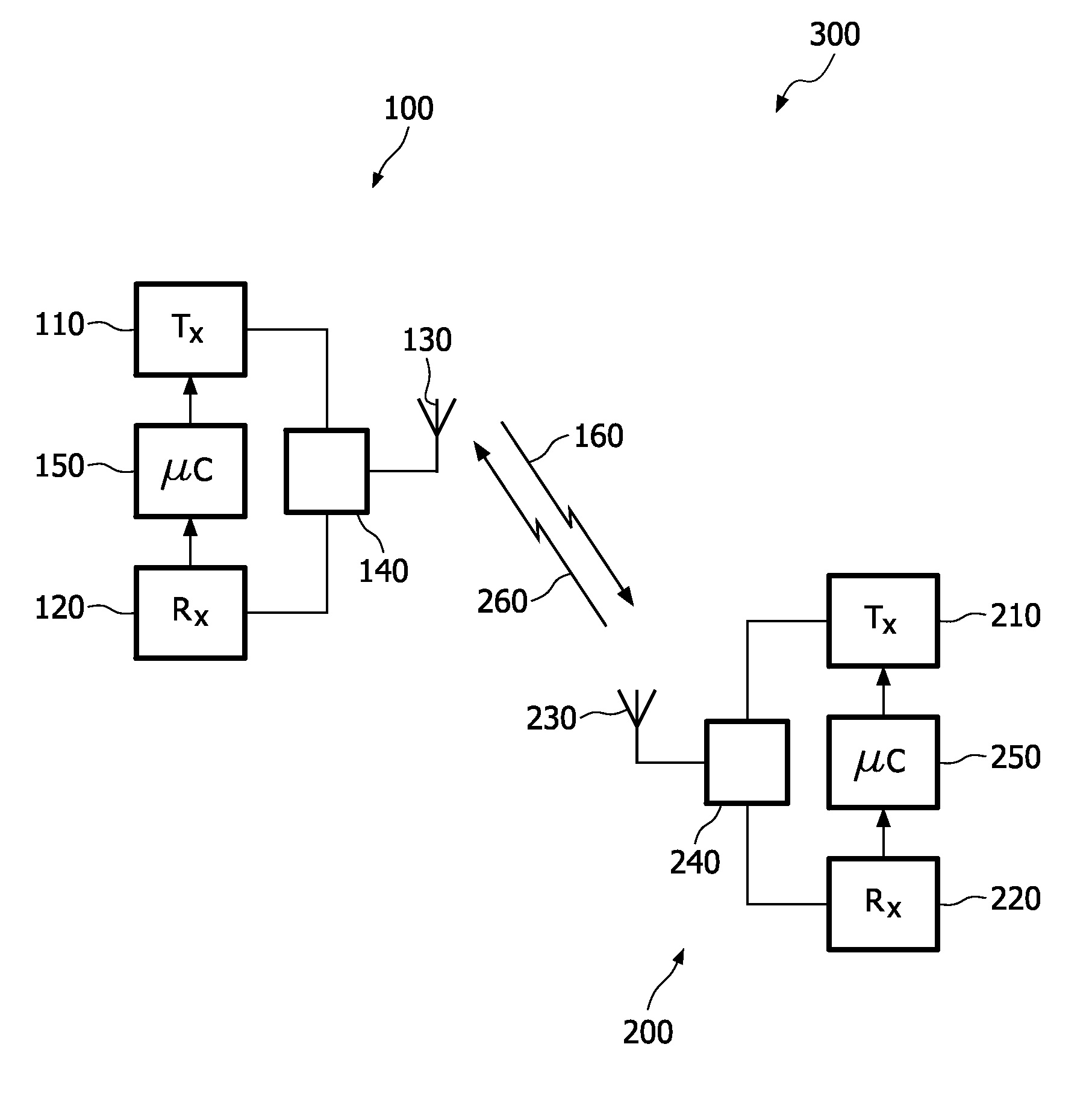
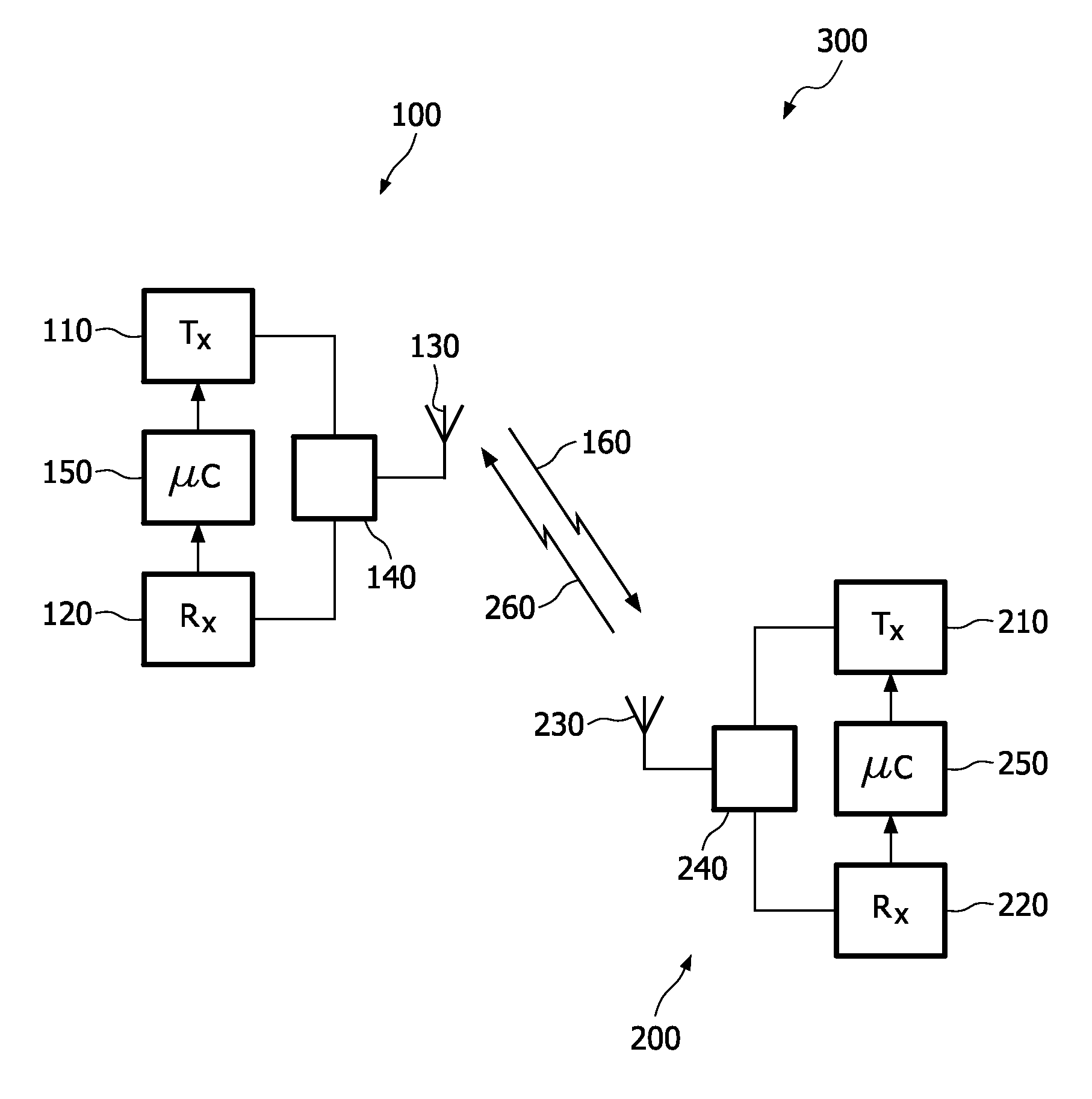
[0020]The present invention relates to a system of communication 300 as depicted on FIG. 1, comprising a primary station 100, like a base station, and at least one secondary station 200 like a mobile station.

[0021]The radio system 300 may comprise a plurality of the primary stations 100 and / or a plurality of secondary stations 200. The primary station 100 comprises a transmitter means 110 and a receiving means 120. An output of the transmitter means 110 and an input of the receiving means 120 are coupled to an antenna 130 by a coupling means 140, which may be for example a circulator or a changeover switch. Coupled to the transmitter means 110 and receiving means 120 is a control means 150, which may be for example a processor. The secondary station 200 comprises a transmitter means 210 and a receiving means 220. An output of the transmitter means 210 and an input of the receiving means 220 are coupled to an antenna 230 by a coupling means 240, which may be for example a circulator ...


PUM


Abstract

The present invention relates to a method for communicating in a network comprising a primary station and at least one secondary station, said secondary station comprising a buffer containing data packets to be transmitted to the primary station, the method comprising the step of the secondary station transmitting an indication of the buffer status to the primary station, said indication comprising information about history of said buffer.

Description

FIELD OF THE INVENTION[0001]The present invention relates to a method for communicating in a network and to radio stations carrying out this method. More specifically, this invention may be implemented in a mobile communication network, like a UMTS system.BACKGROUND OF THE INVENTION[0002]Many communication systems operate using a centralised scheduler which is responsible for allocating transmission resources to different nodes. A typical example is the uplink of the UMTS LTE (Long Term Evolution), where the uplink transmissions from different secondary stations or mobile station or User Equipments (UEs) are scheduled in time and frequency by the primary station or base station or Node B (eNB). The primary station transmits a “scheduling grant” message to a secondary station, indicating a particular time-frequency resource for the secondary station's transmission typically around 3 ms after the transmission of the grant message. The grant message also typically specifies the data ra...

Claims


Application Information

Patent Timeline
Patent Type & Authority Patents(United States)
IPC IPC(8): H04L12/54H04L12/26H04L47/30
CPCH04L47/10H04W28/0278H04W72/085H04L47/30H04L47/33H04W72/04H04W72/12H04W72/542H04W72/543H04W72/1221
Inventor BUCKNELL, PAULTESANOVIC, MILOSBAKERMOULSLEY, TIMOTHY J.
Owner KONINK PHILIPS ELECTRONICS NV
Learn More