
Path computation systems and methods in optical networks

a computation system and optical network technology, applied in the field of optical network, can solve the problems of a regenerator with a higher cost of bias path computation over the regenerator, and achieve the effect of higher cost of bias path computation

Active Publication Date: 2014-03-25
CIENA
View PDF27 Cites 36 Cited by
  • Summary
  • Abstract
  • Description
  • Claims
  • Application Information

AI Technical Summary

Benefits of technology

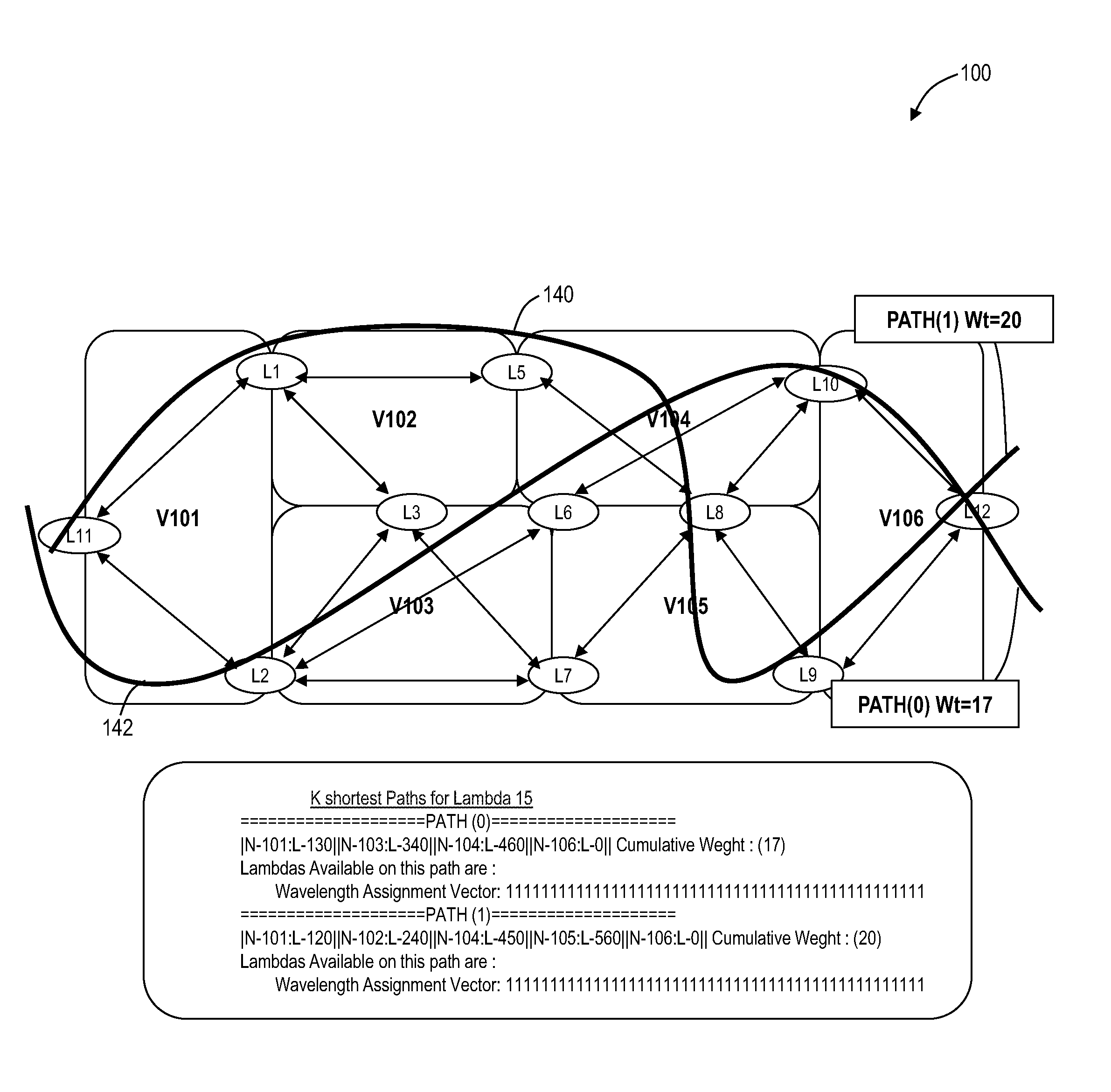
[0005]The method may further include modifying the graph model to reflect the photonic constraints through labeling thereby avoiding a process of transforming the graph model. The method may further include performing the constrained path computation in the network using Dijkstra's algorithm on the modified graph model of the network. The method may further include, for a regenerator at one of the nodes, providing a directed edge (loopback) associated with the regenerator with a higher cost to bias path computation over the regenerator. The method may further include maintaining bit vectors for each of the wavelength capability constraints and wavelength availability constraints at each node in the network; maintaining a connectivity list for the nodal connectivity constraints of each node in the network; and communicating the bit vectors and the connectivity list utilizing a control plane. The method may further include computing disjoint paths with a modification of Suurballe's algorithm. This method may further include performing two iterations of Dijkstra's algorithm on a modified graph model to compute the disjoint paths, wherein a first iteration returns a shortest path while labeling links and nodes and computing disjoint weights for a second iteration, and wherein the second iteration returns shortest paths based on the disjoint weights; and correlating the shortest paths from the two iterations while maintaining the photonic constraints associated therewith.

Problems solved by technology

The method may further include, for a regenerator at one of the nodes, providing a directed edge (loopback) associated with the regenerator with a higher cost to bias path computation over the regenerator.

Method used


Image

  • Path computation systems and methods in optical networks
  • Path computation systems and methods in optical networks
  • Path computation systems and methods in optical networks

Examples


Embodiment Construction

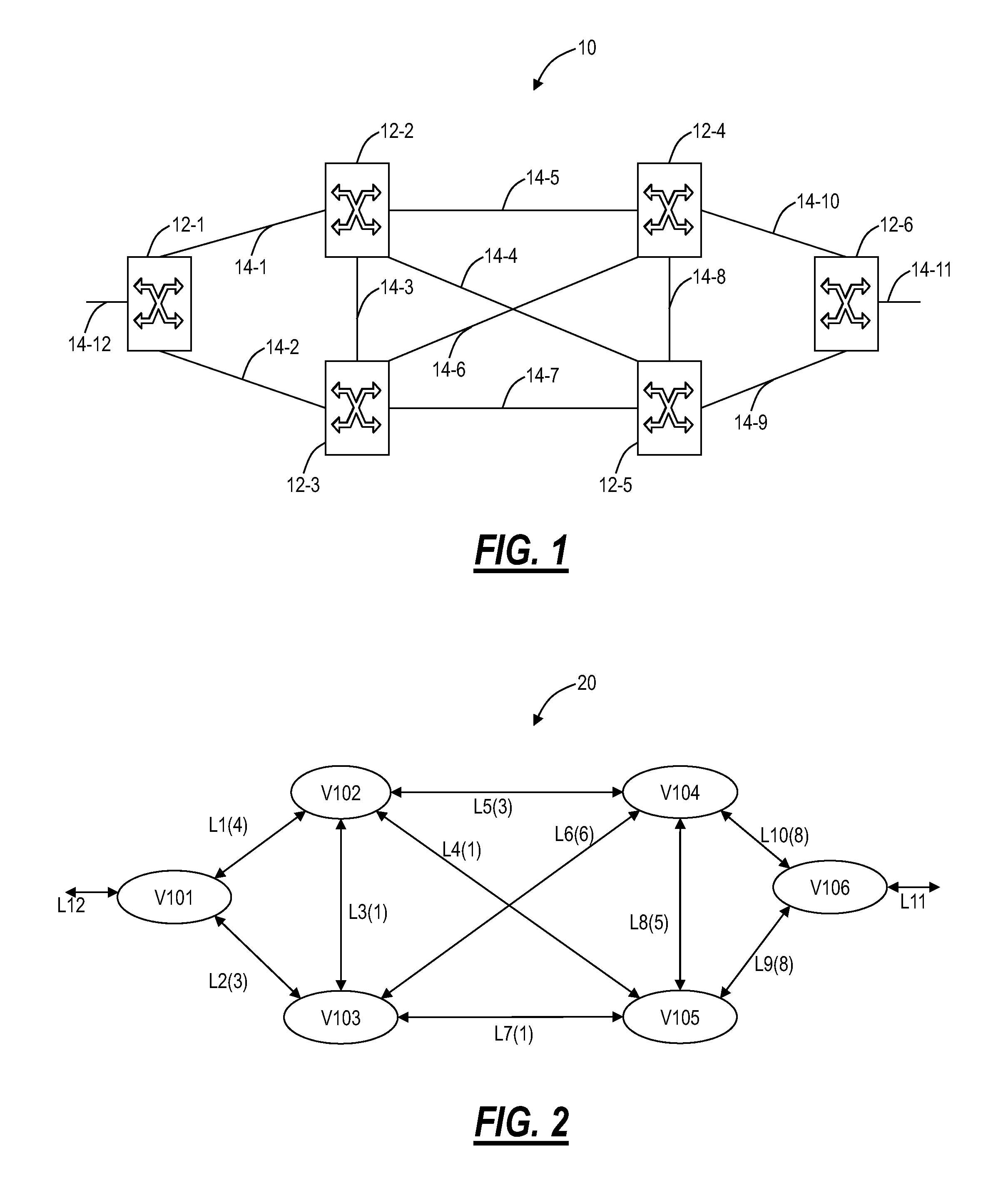
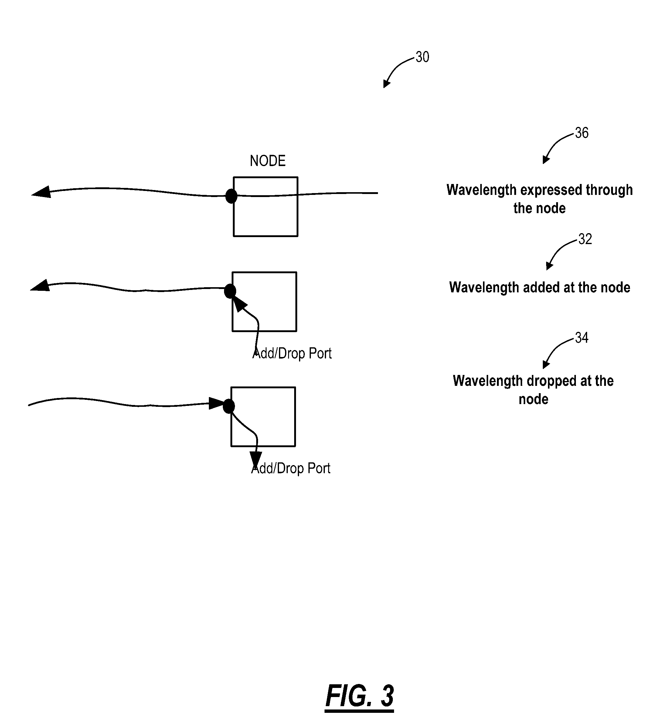
[0027]In various exemplary embodiments, path computation systems and methods in mixed photonic and digital mesh networks define additional constraints required for paths in photonic network. The path computation systems and methods include shortest path algorithm that uses these constraints to compute paths in the photonic network. The definition of these constraints forms an important aspect of path computation algorithm to deliver an optimal path which follows wavelength continuity constraints. The constraints defined for the photonic network could fall into two broad categories, link constraints and nodal constraints. Routing in the electrical domain assumes that each node supports non-blocking switching, hence the computations for the digital network only use link constraints. In the photonic domain, the link constraints are extended to include not only resource availability but also resource capabilities as described herein. The Nodal constraints originate from the fact that th...


PUM


Abstract

A path computation method includes defining photonic constraints associated with a network, wherein the photonic constraints include wavelength capability constraints at each node in the network, wavelength availability constraints at each node in the network, and nodal connectivity constraints of each node in the network, and performing a constrained path computation in the network using Dijkstra's algorithm on a graph model of the network with the photonic constraints considered therein. An optical network includes a plurality of interconnected nodes each including wavelength capability constraints, wavelength availability constraints, and nodal connectivity constraints, and a path computation element associated with the plurality of interconnected photonic nodes, wherein the path computation element is configured to perform a constrained path computation through the plurality of interconnected nodes using Dijkstra's algorithm on a graph model with the photonic constraints considered therein.

Description

CROSS-REFERENCE TO RELATED APPLICATION(S)[0001]The present non-provisional patent claims the benefit of priority of co-pending Indian Patent Application No. 287 / DEL / 2012, filed on Feb. 2, 2012, and entitled “PATH COMPUTATION SYSTEMS AND METHODS IN OPTICAL NETWORKS,” the contents of which are incorporated in full by reference herein.FIELD OF THE INVENTION[0002]Generally, the field of art of the present disclosure pertains to optical networking, and more particularly, to path computation systems and methods in optical networks considering link constraints and nodal constraints associated therewith.BACKGROUND OF THE INVENTION[0003]Distributed control planes have been used in communications networks for some time, gaining on popularity due to increased scalability and resiliency of a distributed management solution over a centralized management solution. In photonic domains, deployment of distributed control plane solution has been slow and initial deployments have only limited function...

Claims


Application Information

Patent Timeline
Patent Type & Authority Patents(United States)
IPC IPC(8): H04J14/00
CPCH04J14/0284H04J14/0267H04J14/0258H04J14/0215H04J14/0271H04J14/0217H04J14/0206H04J14/0257H04J14/0269
Inventor PRAKASH, ANURAGCHHILLAR, MOHITTRNKUS, MARIANKHAN, WASEEM REYAZ
Owner CIENA
Learn More