Internal valve and methods of use for inflatable objects

a technology of inflatable objects and internal valves, which is applied in the field of inflatable objects with internal valves, can solve the problems of increasing the risk of injury, structural instability of inflatable objects, and the side of the chair tending to distort, so as to improve the air pressure, improve the stability of inflatable objects, and improve the effect of stability

Inactive Publication Date: 2014-04-01
ZHANG ZHENGPING
View PDF18 Cites 0 Cited by
  • Summary
  • Abstract
  • Description
  • Claims
  • Application Information

AI Technical Summary

Benefits of technology

[0021]This invention presents an internal valve for inflatable objects and methods of use thereof to address the issues or problems in the prior art as described above. In accordance with several embodiments, the internal valve comprises: 1) a conventional check valve, and 2) a discharging means for external control. The internal valve is a novel and simple modification to conventional check valves with the addition or integration of the discharging means for external control. The internal valve provides the only passage from a main chamber to a separate stabilizing or reinforcing supplemental chamber. Air inflates the main chamber through a standard valve and then, after the pressure inside reaches a certain level, inflates the supplemental chamber. The supplemental chamber is secured such that the air pressure in the main chamber cannot significantly reduce or depress its volume. Thus this prevents the premature occurrence of a balance between both sides of the internal valve before the supplemental chamber fills up. As a result, the air in the supplemental chamber cannot flow back to the main chamber, even under external pressure, and therefore the reinforced supplemental chamber strengthens the inflatable objects. Furthermore, the supplemental chamber can retain a higher air pressure after the main chamber slightly deflates.
[0022]The methods of use of the internal valve and conventional check valves have the following fundamental differences. The internal valve 1) can facilitate both inflation and deflation without the use of additional instruments; 2) is designed for an enclosed or isolated internal chamber instead of an open chamber in a flow control system; 3) can be installed to such an isolated chamber at any desired place inside a main chamber rather than only at places near a standard valve of the main chamber; and 4) is designed for use with supplemental chambers for stabilization and reinforcement that can be invisible from the outside of an inflatable object.

Problems solved by technology

Furthermore, because the air inside inflatable objects is substantially movable and compressible, external pressure can easily distort their shapes by forcing the air in edge or corner regions to flow away and redistribute.
This causes inflatable objects to be structurally unstable when used as support systems such as furniture.
For example, when weight is applied at an edge of an inflatable chair, the side of the chair tends to distort.
Such a distortion can cause a person to slip from the seating surface, increasing the person's risk of injury.
This problem becomes more significant as the height of the support system increases.
However, these tubes or chambers need to be inflated through multiple external conventional valves.
Unfortunately, the extra valves may cause poor air retention if cheap conventional valves are used, as usually do, in such applications as inflatable furniture.
Yet some designs also require manual assembly of independent parts.
Furthermore, a single built-in pump cannot work without a complex air distribution system.
However, since the air loss can only be slowed rather than eliminated, the design cannot provide stability under constant pressures or forces.
In all the approaches described above, stabilizing or reinforcing parts most likely add additional profiles that can make inflatable products less attractive.
However, unlike the chambers described in the prior art, these sub-chambers may have no other air passages or discharging means.
Unfortunately, to deflate the sub-chambers, one must insert a long instrument through the external valve to open each of the check valves.

Method used


Image

  • Internal valve and methods of use for inflatable objects
  • Internal valve and methods of use for inflatable objects
  • Internal valve and methods of use for inflatable objects

Examples


Embodiment Construction

—PREFERRED EMBODIMENTS—FIGS. 1-3

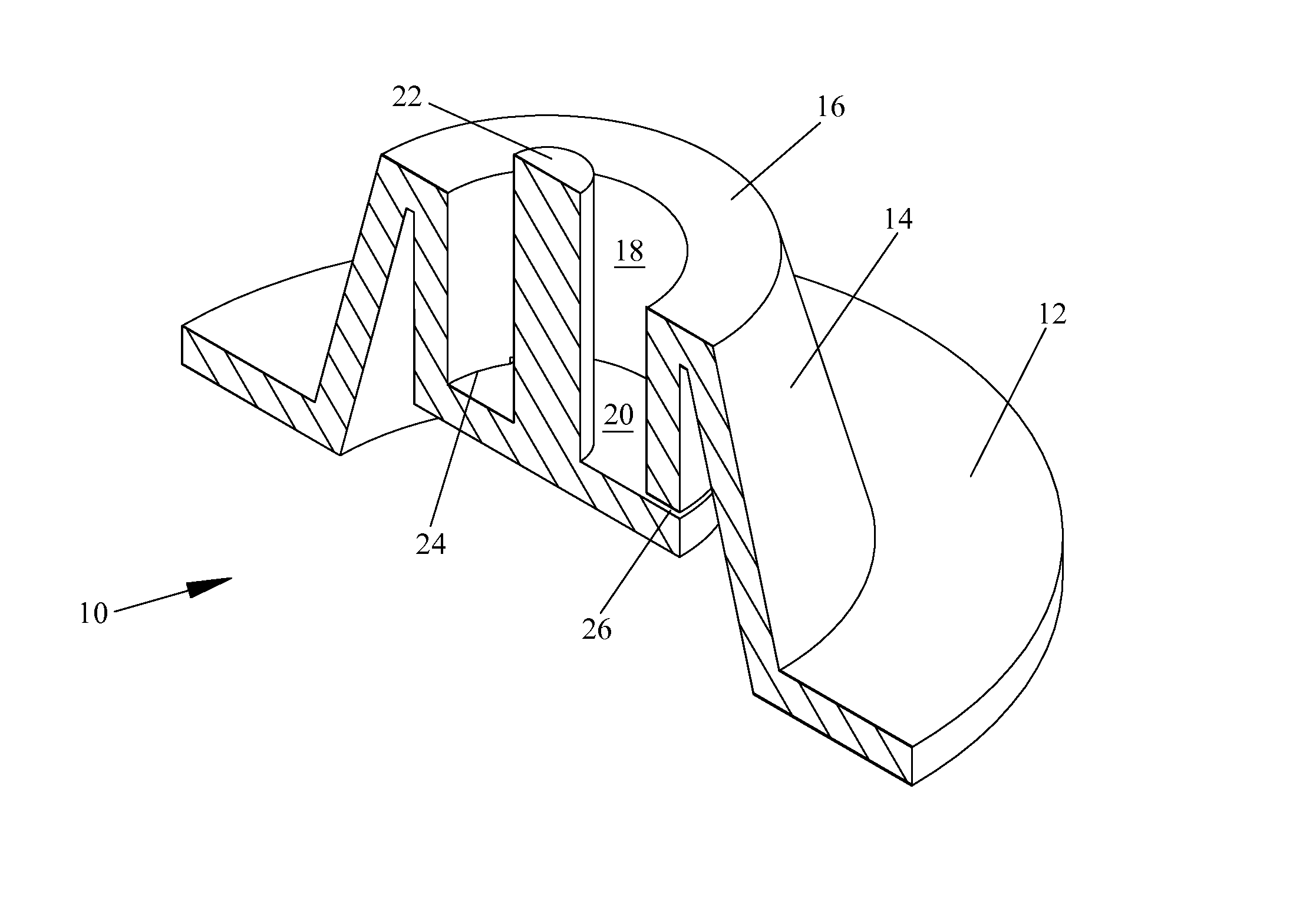
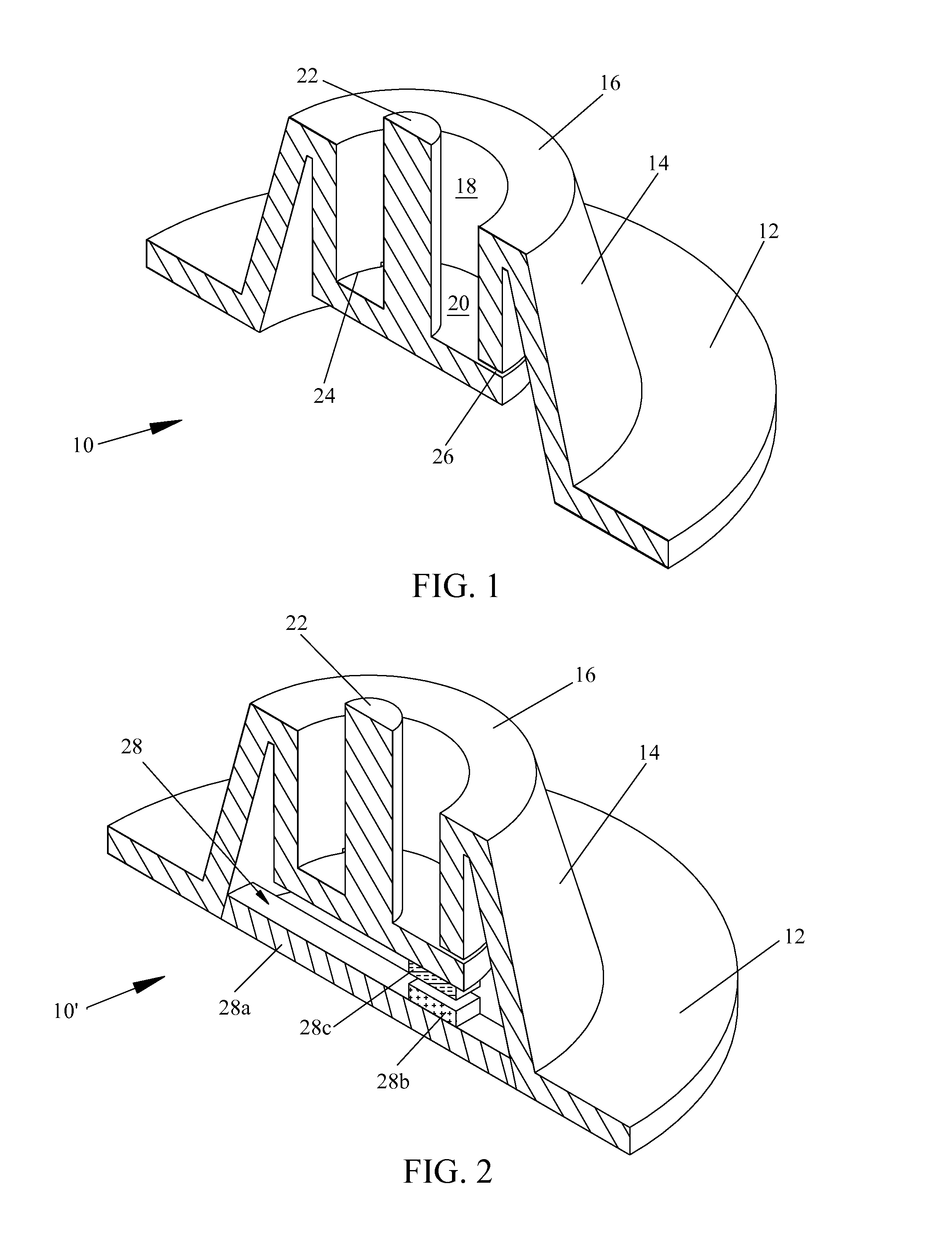
[0031]A preferred embodiment of the internal valve of the present invention is illustrated in FIG. 1. An internal valve 10 comprises an annular valve seat 12, a conical wall or diaphragm 14, an annular connection 16, a tube or tubular member 18, a check flap 20 and a discharging cylinder or finger 22. Wall 14 extends upwardly from seat 12 and connects with the top of tube 18 through connection 16. The body of the tube extends downwardly. The flap is connected with the bottom of the tube partially by a hinge 24 and functions as a check valve. The flap is preferably formed from the bottom wall of tube 18 that is partially severed from the body by a shearing cut 26, as known in the art. One end of finger 22 is secured substantially to the center of flap 20 inside the tube and the other end is extended above the top surface of connection 16 outside the tube. Therefore, the flap moves to an open position if finger 26 is pushed down. Valve 10 is preferably ...


PUM


Abstract

An internal valve (10, 10′ or 10″) and its methods of use for stabilizing and reinforcing inflatable objects are disclosed. The internal valve is a novel, simple modification to conventional check valves with the addition of a discharging means (14, 22 or 28)for external control. An internal supplemental chamber comprises one or more partitions that are secured, directly or by I-beams (40′), to main chamber's walls (40) of an inflatable object and stretched when the main chamber is inflated. With the internal valve as the passage to and from the main chamber, the enclosed or isolated supplemental chamber (30, 30′, 32, 34, 36 or 38) functions as a stabilizing or reinforcing component. A plurality of chambers 36 can form cylinder beams for an inflatable mattress.

Description

CROSS-REFERENCE TO RELATED APPLICATIONS[0001]Not ApplicableFEDERALLY SPONSORED RESEARCH[0002]Not ApplicableBACKGROUND OF THE INVENTION[0003]1. Field of Invention[0004]This invention generally relates to valves for inflatable objects, specifically to a novel modification to conventional check valves and its methods of use for the purpose of improving the stability and style of inflatable objects.[0005]2. Prior Art[0006]Inflatable products are typically fashioned from flexible polymer materials such as polyvinylchloride. As the strength of flexible polymer materials has improved, more inflatable products, including inflatable furniture, have become available. Inflatable products can be large, light, attractive and cheap; they can be readily inflated and used or deflated and stored in very small spaces; and they can be easily cleaned.[0007]Inflatable objects are generally somewhat balloon-like. Their stiffness and bounciness depend partly on their level of inflation and their configura...

Claims


Application Information

Patent Timeline
Patent Type & Authority Patents(United States)
IPC IPC(8): A47C27/10
CPCF16K15/185F16K15/202A47C27/081Y10T137/7876F16K15/1825
Inventor ZHANG, ZHENGPING
Owner ZHANG ZHENGPING
Why Eureka
Try Eureka