
Concealable TV mount extends and rotates

a technology of extending and rotating tvs and mounting systems, which is applied in the direction of reading racks, electrical apparatus casings/cabinets/drawers, instruments, etc., can solve the problems of over-reaching of televisions in the home, and achieve the effect of preventing damage to tvs, reducing the force required, and sufficient adjustability

Active Publication Date: 2014-04-01
BESHARA MARK JOSEPH
View PDF27 Cites 26 Cited by
  • Summary
  • Abstract
  • Description
  • Claims
  • Application Information

AI Technical Summary

Benefits of technology

The present invention describes a mount that can hold various appliances against a wall or ceiling, allowing them to be positioned in different ways for easy access. The mount is completely concealed when not in use and can safely hold the appliance. The mount has adjustable attachment mechanisms for different sized appliances to prevent damage. The linkage arms guide the appliance through a defined path and minimize the force required to open or close the mounting system. The weight of the mounting system components is balanced to equalize forces. The technical effects of the invention allow for convenient and safe mounting of various appliances, with easy access and adjustability for different sizes and shapes.

Problems solved by technology

However, in order to do so comfortably would require that the television be mounted high on a wall or in a ceiling, which is at odds with conventional home décor.
Another concern of some people is that to be easily viewable a television often demands an overly prominent place in a home or office.

Method used


Image

  • Concealable TV mount extends and rotates
  • Concealable TV mount extends and rotates
  • Concealable TV mount extends and rotates

Examples


Embodiment Construction

[0134]The mounting systems and associated methods described here may be used wherever it is desired to store an appliance in a concealed manner, while supporting it in such a state that it is readily accessible when it is necessary to operate the appliance. The appliance can be concealed on, or in, a wall, a ceiling, or under a countertop. Although the presently described mounting system will accommodate a variety of appliances, the focus of the following discussion will relate to storage and use of the general class of flat-panel televisions.

[0135]As described here, a mechanical system supports an appliance and rotates it into a desired position for operation as the appliance is moved away from a supporting structure. Any appliance can be described as having an operational or working face that must be available to a user when it is in a working position for use. In the case of a TV the working face is the display side and a working position is any orientation that allows a user to ...


PUM


Abstract

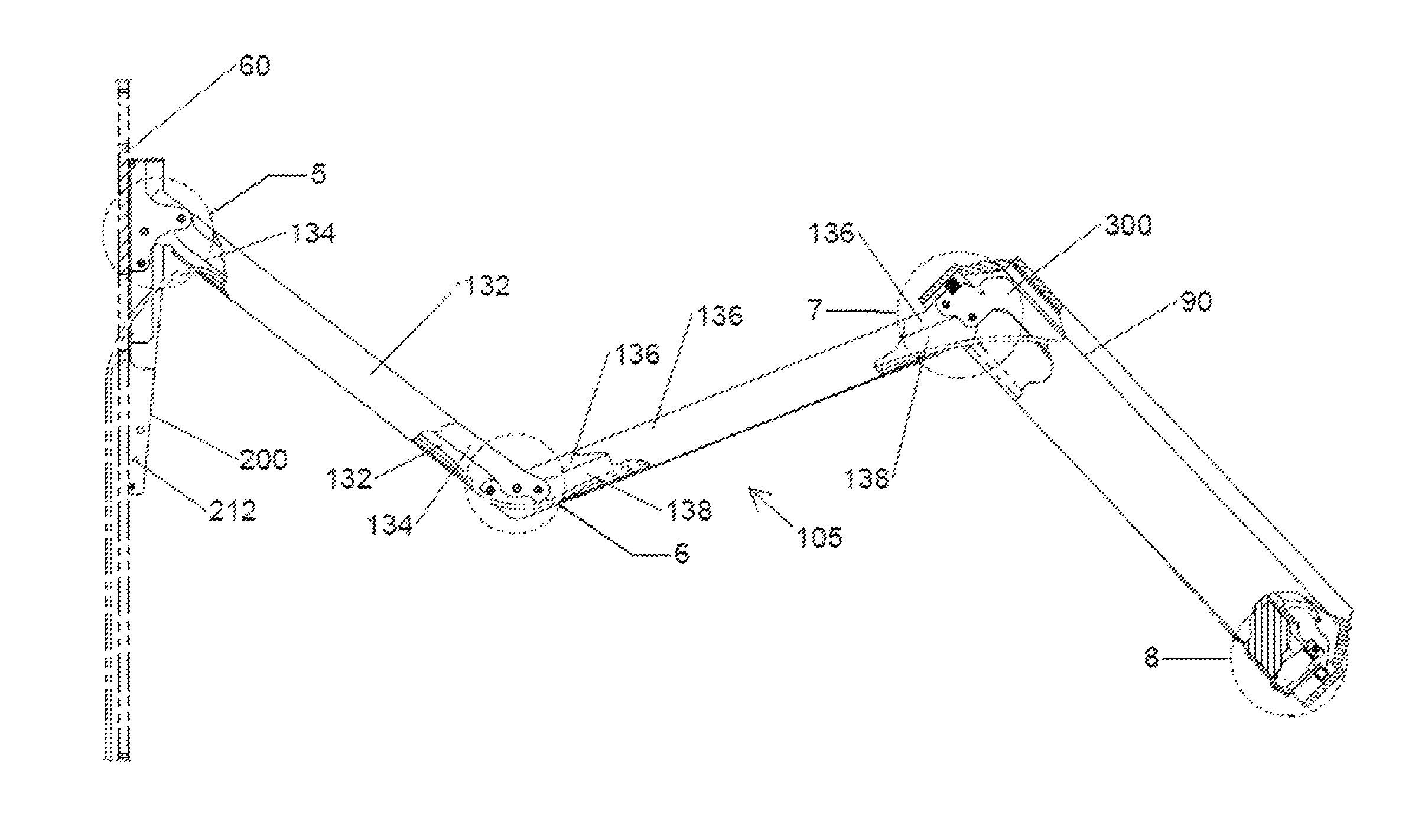
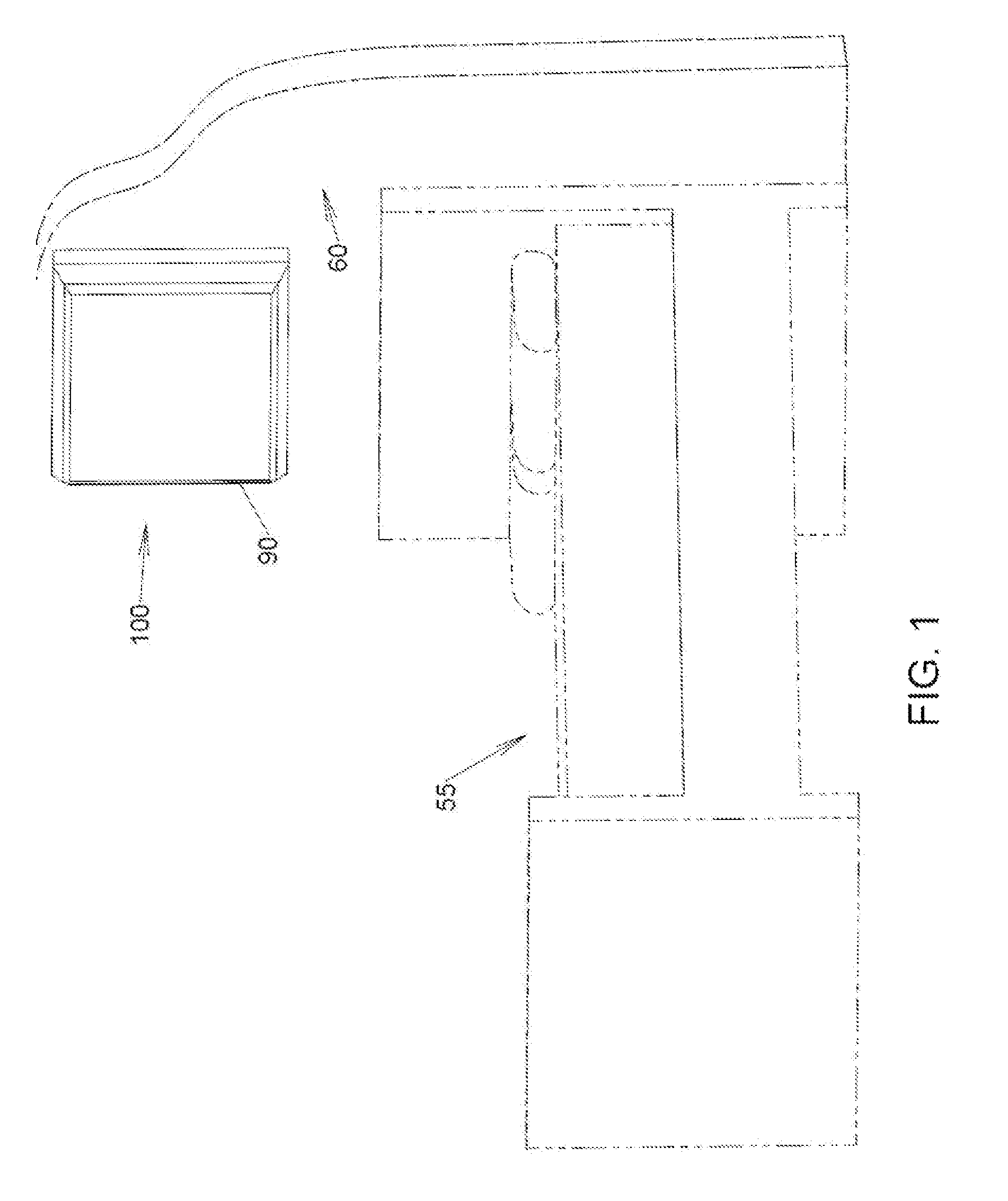
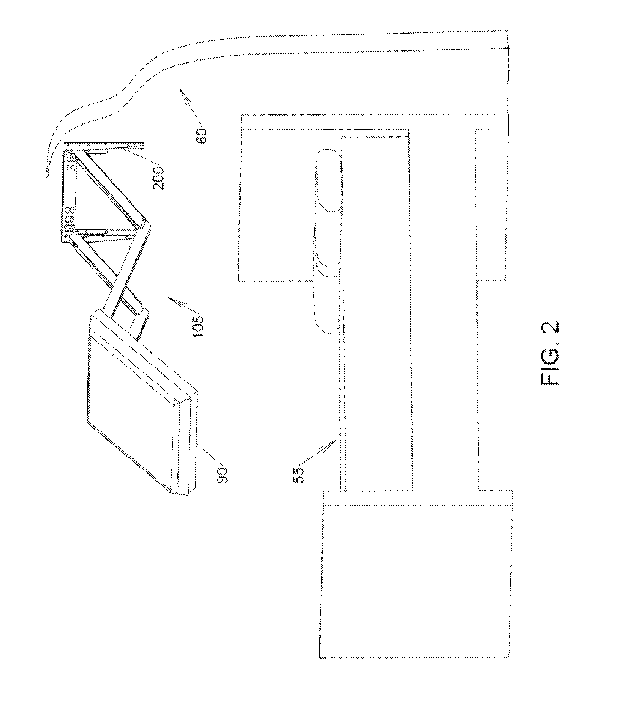
This mounting system can be used to house a television or other appliance against, or in, a wall, ceiling, floor or table. A user may manipulate the position and orientation of the housed appliance from its storage position to an operational position. The entire system can be completely concealed from view by a decorative cover while providing ready access to the appliance. To operate the appliance, the mount provides for extension and / or rotation to a desired position without removal of the concealing cover. A mounting bracket is attached to a fixed structure, and an appliance interface bracket is adapted for attachment to the appliance. A system of linkage arms couples the two brackets. Multiple linkage arm systems accommodate various lengths of extension and degrees of rotation including 180°. In all cases provision is made for concealed containment of all power and control cables necessary for operation of the appliance.

Description

CROSS-REFERENCES TO RELATED APPLICATIONS[0001]This application claims benefit of U.S. Provisional Application No. 61 / 320,263, filed Apr. 1, 2010, entitled “Extendable Mount for Flat-Panel Display”, which is incorporated here by reference in its entirety.[0002]This application claims benefit of U.S. Provisional Application No. 61 / 405,576, filed Oct. 21, 2010, entitled “Operable Appliance Mount”, which is incorporated here by reference in its entirety.FIELD OF THE INVENTION[0003]The present invention relates generally to mounting systems for flat-panel displays, and more particularly to selectively adjustable flat-panel display mounting systems.BACKGROUND OF THE INVENTION[0004]It is common to view television from a recumbent or resting position. However, in order to do so comfortably would require that the television be mounted high on a wall or in a ceiling, which is at odds with conventional home décor. Another concern of some people is that to be easily viewable a television often ...

Claims


Application Information

Patent Timeline
Patent Type & Authority Patents(United States)
IPC IPC(8): A47F5/00F16M11/00
CPCA47B23/007F16M11/048F16M11/10F16M11/18F16M13/02F16M13/027F16M2200/041F16M2200/063F16M2200/065
Inventor BESHARA, MARK JOSEPH
Owner BESHARA MARK JOSEPH
Learn More