Mobile tool facility

a technology of mobile tools and facilities, applied in the field of monitoring and tracking objects, can solve the problems of many inventory items being misused, misplaced, improperly tracked and replenished by the employees of the company, and the system lacks tracking information, cost accounting information, security methods, and replenishment information. to achieve the effect of reducing the amount of electromagnetic energy

Active Publication Date: 2014-04-01
JS2 LOGISTIC SOLUTIONS LLC
View PDF19 Cites 31 Cited by
  • Summary
  • Abstract
  • Description
  • Claims
  • Application Information

AI Technical Summary

Problems solved by technology

Companies typically have difficulties tracking inventory items and their usage within their facilities.
Many inventory items are misused, misplaced, and improperly tracked and replenished by the employees of the companies.
However, these systems still lack tracking information, cost accounting information, security methods, and replenishments information in the process of tracking and monitoring the items stored in the controlled space and linking the responsible employee with the items being taken in and out of the controlled space.
The problem escalates when outside of a controlled environment such as a facility.
Jobsite equipment theft is significant with industry loss estimates up to one billion dollars annually, according to a 2003 National Equipment Register study.
Tool tracking and management systems provide one level of security, but a large percentage of theft includes tools disappearing from jobsites at the end of the workday.
However, these solutions still lack the tracking and access control that is beneficial on a jobsite with combinations of employees and contractors, as well as ease and portability of the secured area.

Method used


Image

  • Mobile tool facility
  • Mobile tool facility
  • Mobile tool facility

Examples


Embodiment Construction

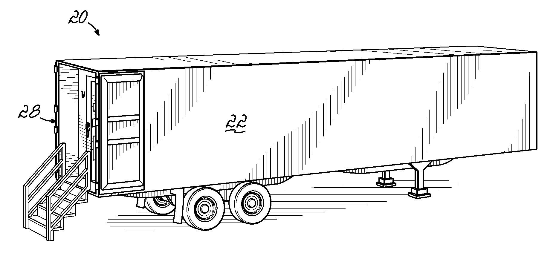
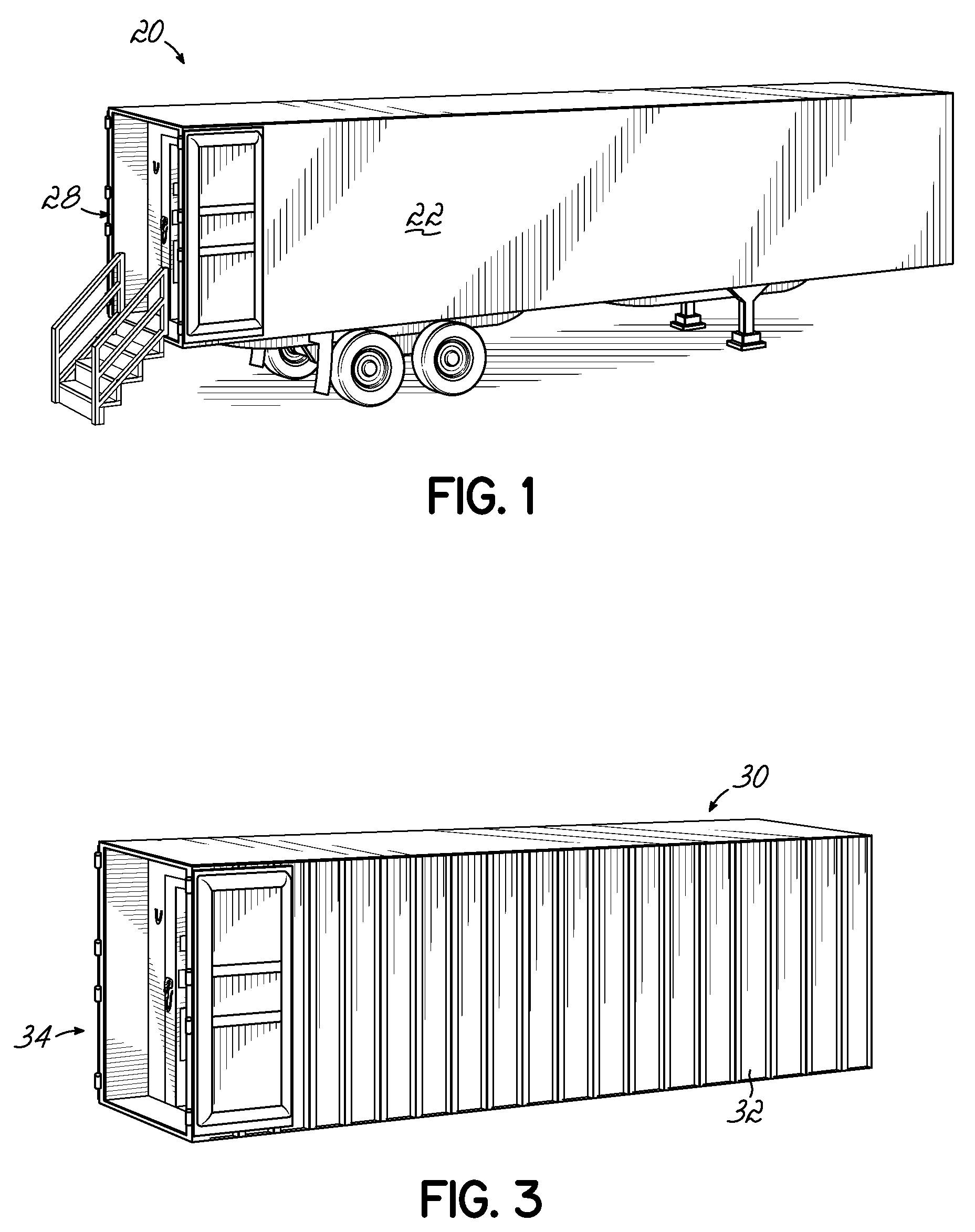
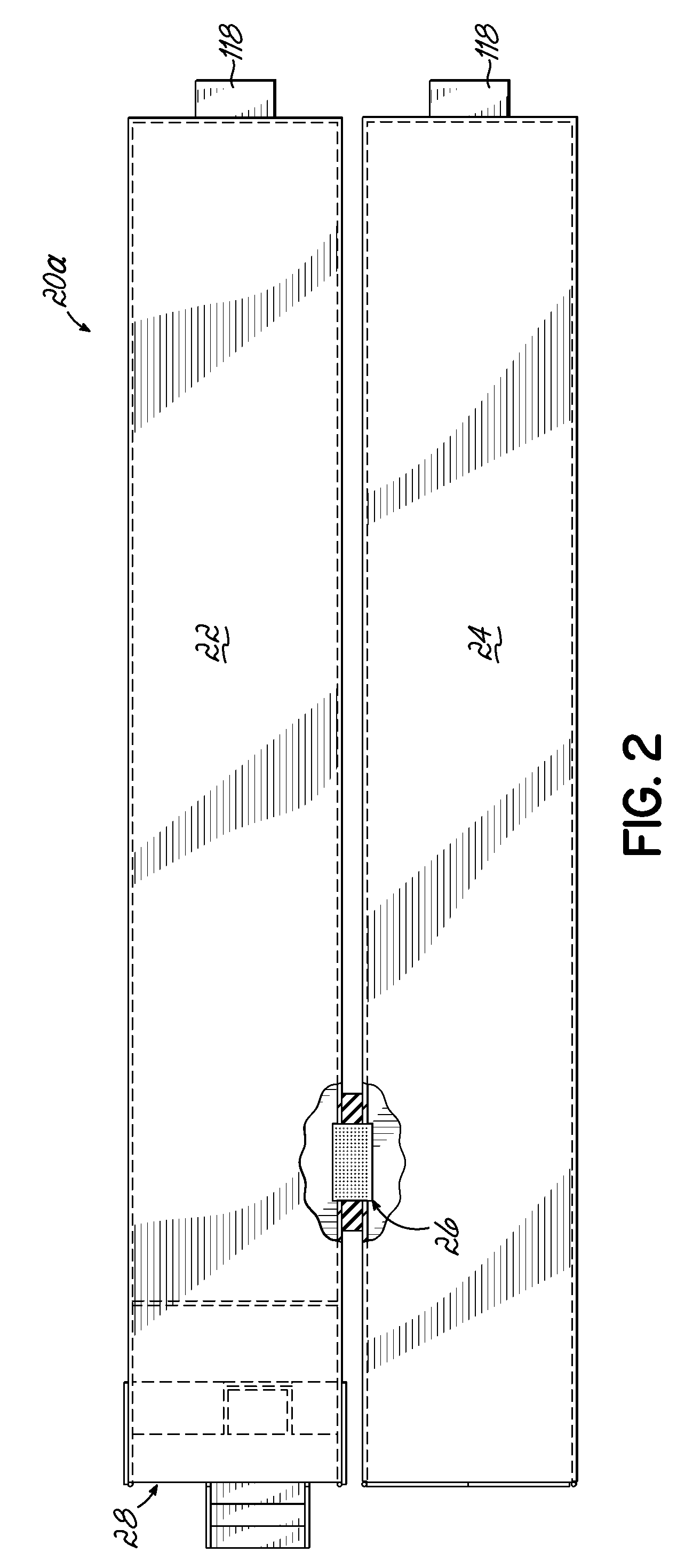
[0026]Embodiments of the invention provide a mobile tool facility that utilizes radio frequency identification (“RFID”) with a security portal system. The security portal system provides a controlled access point to the mobile tool facility. As seen generally in FIG. 1, a mobile tool facility 20 may be implemented in a trailer 22, such as a standard 53 foot trailer, though other sized trailers may also be used depending on the space requirements needed for the controlled access. Smaller controlled spaces may be implemented in trailers of lengths 28-48 feet, while other spaces may require spaces exceeding a standard 53 foot trailer. In these latter instances and as seen in FIG. 2, multiple trailers 22, 24 may be parked next to one another, with an access 26 between the trailers as seen in FIG. 2. Here the first trailer 22 provides the controlled access point 28 and part of the controlled area, while the second trailer 24 provides additional space and is accessible only through the fi...


PUM


Abstract

A mobile tool facility is provided having a container configured to be moved to a plurality of locations. A portal system is positioned in an interior of the container and spaced from a container end allowing access to the portal system. The portal system is operable to control access into and out of the container. A radio frequency shield wall is positioned in the interior of the container and spaced from the portal system allowing access between the portal system and the shield wall. The shield wall is configured to reduce an amount of electromagnetic energy entering the interior of the container. An auxiliary power unit associated with the container is operable to provide power to the portal system. A plurality of items stored in the interior of the container in a controlled space is available to be removed from the container through the portal system by an authorized individual.

Description

FIELD OF THE INVENTION[0001]The invention is generally related to monitoring and tracking objects and items, and more particularly, to systems, devices and methods for monitoring and tracking objects in a controlled space.BACKGROUND OF THE INVENTION[0002]Companies typically have difficulties tracking inventory items and their usage within their facilities. Many inventory items are misused, misplaced, and improperly tracked and replenished by the employees of the companies. Therefore, companies have incentives to track the items, hold employees responsible for missing items, properly account costs, and replenish the missing items based on demand. Typically items of the inventory are kept in a controlled space that is monitored. Some companies have used locking doors with keypads that allow only employees with authorized code to enter the controlled space. In addition, computers and bar code tags have been used to track the items in and out of the controlled space. However, these syst...

Claims


Application Information

Patent Timeline
Patent Type & Authority Patents(United States)
IPC IPC(8): G06F7/04B60R25/00G05B19/00G05B23/00H04Q1/00H04B1/00G08B29/00H04Q9/00H04B3/00G06F7/00G08C19/00
CPCG07C9/00912G07C9/00111G07C2009/00793Y10T70/7068Y10T70/308Y10T70/7057Y10T70/7028G07C9/28
Inventor GREEN, MICHAELHALL, KEVIN
Owner JS2 LOGISTIC SOLUTIONS LLC
Why Eureka
Try Eureka