Thermal management for aircraft auxiliary power unit compartment

a technology for auxiliary power units and aircraft, which is applied in the direction of efficient propulsion technologies, machines/engines, transportation and packaging, etc., can solve the problems lack of inherent ability to protect oil coolers, and bulky and complex current passive cooling systems. , to achieve the effect of limited ability to distribute and ventilate compartment air

Active Publication Date: 2008-03-04
HAMILTON SUNDSTRAND CORP
View PDF7 Cites 48 Cited by
  • Summary
  • Abstract
  • Description
  • Claims
  • Application Information

AI Technical Summary

Benefits of technology

[0008]The invention comprises an improved passive cooling system for an aircraft APU compartment that includes a lightweight annular air-cooled oil cooler that is strategically oriented and shrouded to face its annular inlet axially downstream from the exhaust of the APU to make it inherently fireproof to flames from the APU or any location within the APU compartment that fuel can accumulate.

Problems solved by technology

Thermal management of the auxiliary power unit (APU) compartment for a high-powered aircraft presents a challenge.
Current passive cooling systems are bulky and complex, and their ability to distribute and ventilate compartment air is limited.
Furthermore, they do not have any inherent ability to protect the oil cooler from flames that may emanate from the APU or pooled fuel in the compartment.

Method used


Image

  • Thermal management for aircraft auxiliary power unit compartment
  • Thermal management for aircraft auxiliary power unit compartment
  • Thermal management for aircraft auxiliary power unit compartment

Examples


Embodiment Construction

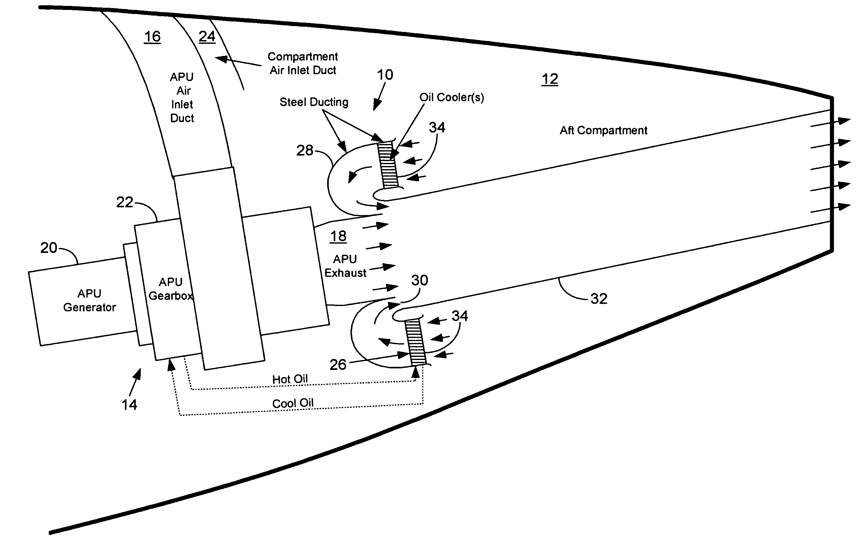
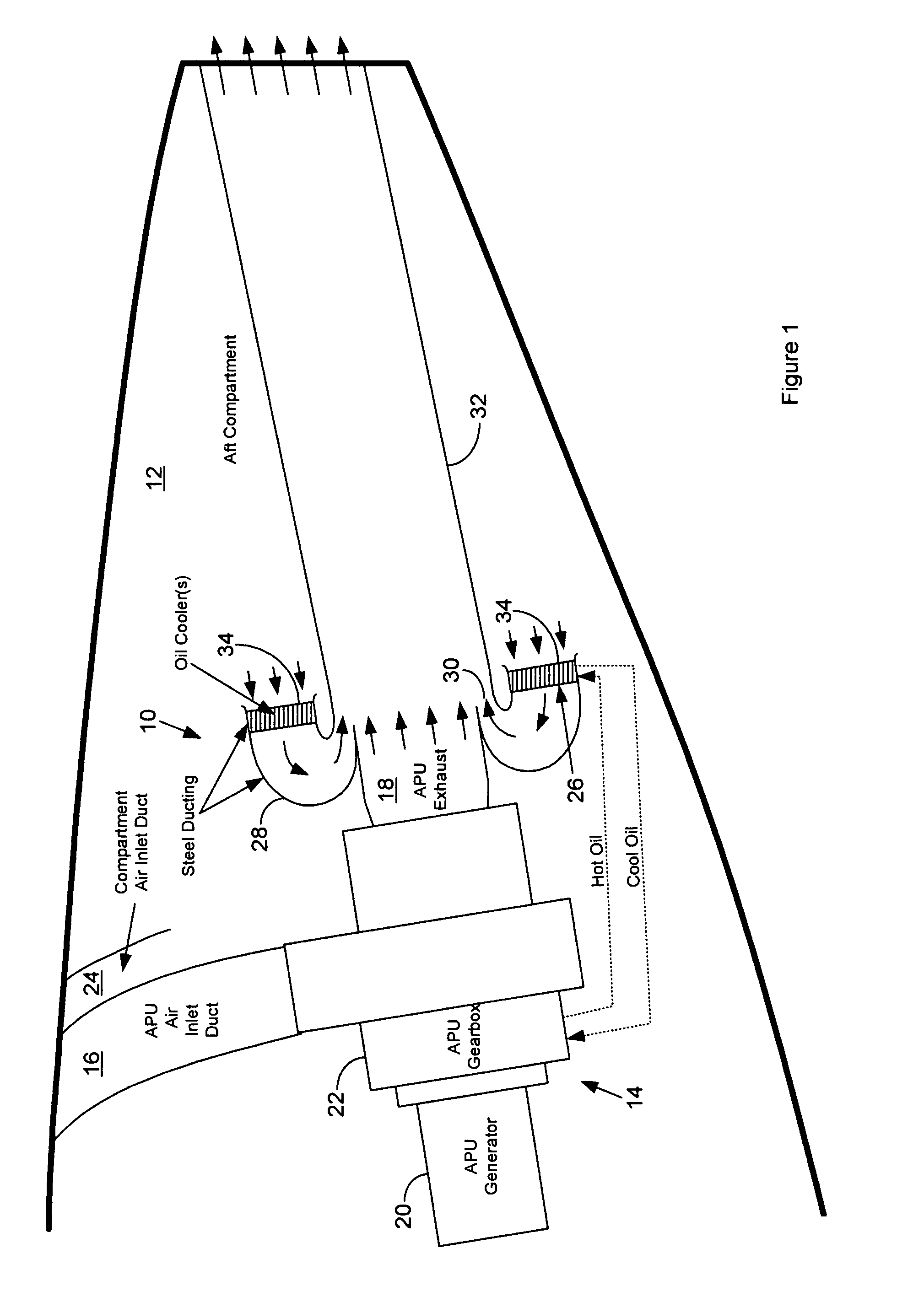
[0011]FIG. 1 is a cut-away side view of a passive APU compartment cooling system 10 according to the invention as positioned in a tail cone APU compartment 12 of an aircraft, and APU 14 with an associated APU inlet duct 16 and exhaust duct 18. APU combustion air enters the APU 14 from ambient through the APU inlet duct 16.

[0012]The APU 14 then compresses the combustion air, adds fuel, and combusts the resulting fuel / air mixture. The resulting hot, high-pressure combustion gas then expands through at least one turbine (not shown) within the APU 14. The turbine generates power for associated devices, such as a generator 20, through a gearbox 22 that is coupled to the turbine.

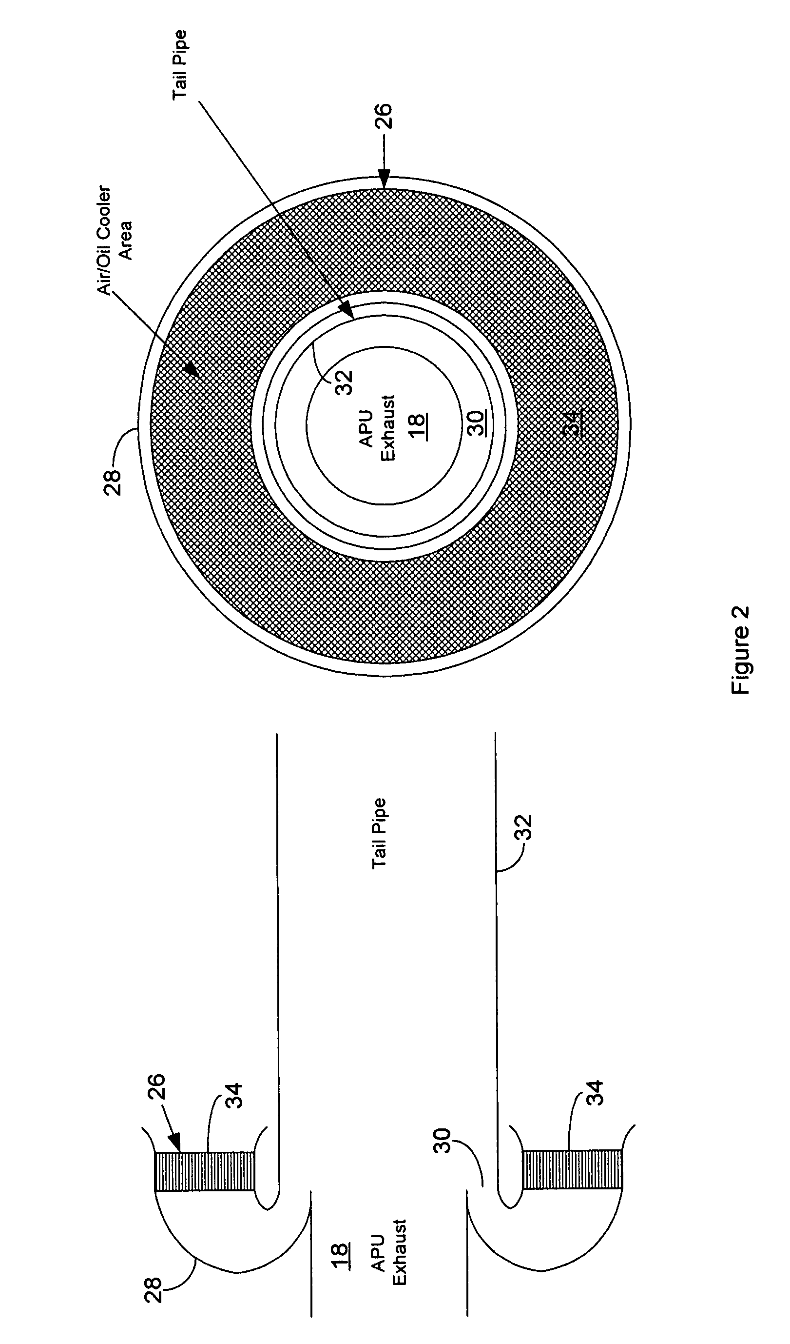
[0013]The spent combustion gas leaving the turbine then exhausts through the exhaust duct 18 at relatively high velocity. Cooling air from ambient enters the compartment 12 through a compartment inlet duct 24. Compartment air flows through the fins of at least one air-cooled annular APU oil cooler 26 and an annula...


PUM


Abstract

An improved passive cooling system for an aircraft APU compartment that includes a lightweight annular air-cooled oil cooler that is strategically oriented and shrouded to face its annular inlet away axially downstream from the exhaust of the APU to make it inherently fireproof to flames from the APU or any location within the APU compartment that fuel can accumulate.

Description

CROSS REFERENCE TO RELATED APPLICATIONS[0001]This Application claims the benefit of the filing date for prior filed co-pending Provisional Application Ser. No. 60 / 510,802, filed 10 Oct. 2003.FIELD OF THE INVENTION[0002]The invention relates to an auxiliary power unit (APU) for aircraft, and more particularly to an improved passive cooling system for thermal management of a compartment housing such APUs.BACKGROUND OF THE INVENTION[0003]Thermal management of the auxiliary power unit (APU) compartment for a high-powered aircraft presents a challenge. A suitable cooling system for such an application must insure that the APU oil, that is, the oil used to lubricate and carry heat away from the APU and the generators that load the APU, as well as the air in the compartment that houses the APU is properly cooled.[0004]Typically, a cooling system generates and directs an air stream through fins of air-cooled APU oil cooler to cool the APU oil. This air stream may comprise ambient air, compa...

Claims


Application Information

Patent Timeline
Patent Type & Authority Patents(United States)
IPC IPC(8): F02C7/06F02G3/00B64D33/08B64D41/00F01D25/12F02C7/12F02C7/25
CPCB64D33/08B64D41/00F01D25/12F02C7/12F02C7/25B64D2033/0213B64D2041/002Y02T50/44Y02T50/671Y02T50/675F05D2220/50F05D2260/601F05D2250/51Y02T50/40Y02T50/60
Inventor HAGSHENAS, BEZHAD
Owner HAMILTON SUNDSTRAND CORP
Why Eureka
Try Eureka