Integrated power and pressurization system

a power and pressurization system technology, applied in the field of integrated systems, can solve the problems of increasing the overall system weight and/or costs

Inactive Publication Date: 2006-10-19
HONEYWELL INT INC
View PDF16 Cites 49 Cited by
  • Summary
  • Abstract
  • Description
  • Claims
  • Application Information

AI Technical Summary

Problems solved by technology

In many instances, each of these functions is implemented using separate subsystems and / or devices, which can increase overall system weight and costs.
Moreover, such design platforms may not rely solely on the electric power from the engine to provide electricity and pressurization air, especially when on the ground or in the unlikely event the engine generators do not operate normally.
It is thus seen that even with the more electric designs, various subsystems and / or devices may be included, which can increase overall system weight and / or costs.

Method used


Image

  • Integrated power and pressurization system
  • Integrated power and pressurization system
  • Integrated power and pressurization system

Examples


Embodiment Construction

[0016] The following detailed description of the invention is merely exemplary in nature and is not intended to limit the invention or the application and uses of the invention. Furthermore, there is no intention to be bound by any theory presented in the preceding background of the invention or the following detailed description of the invention.

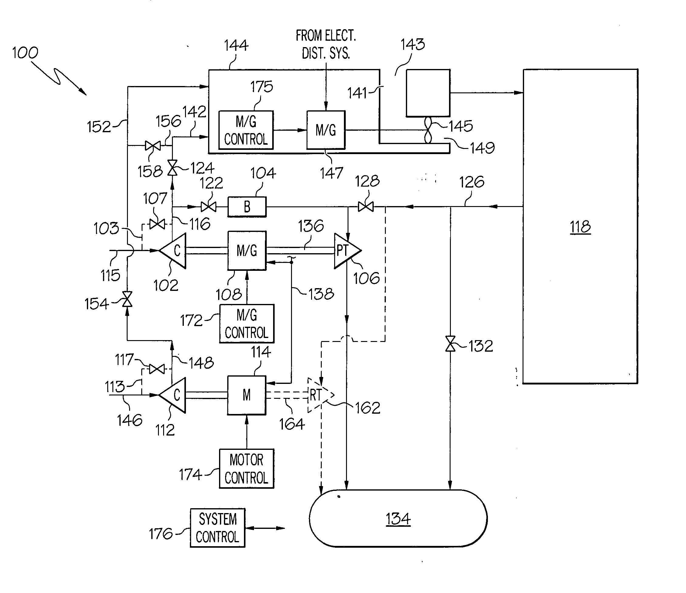
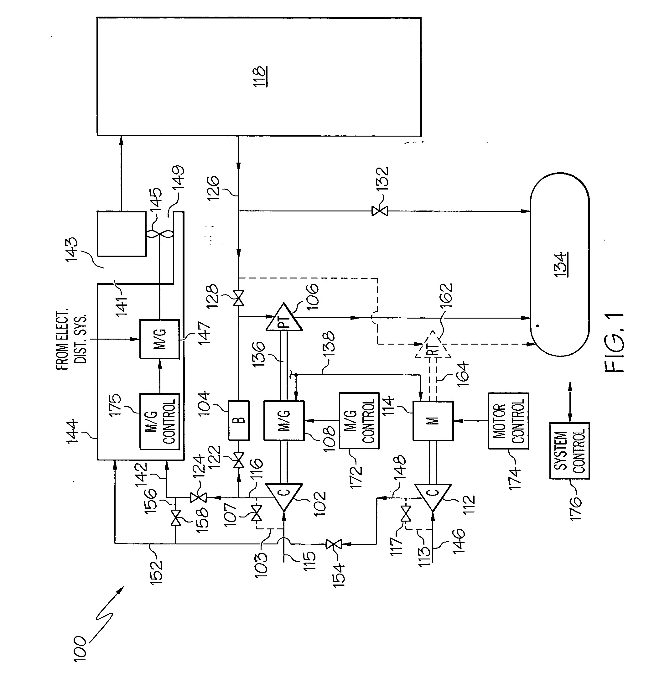
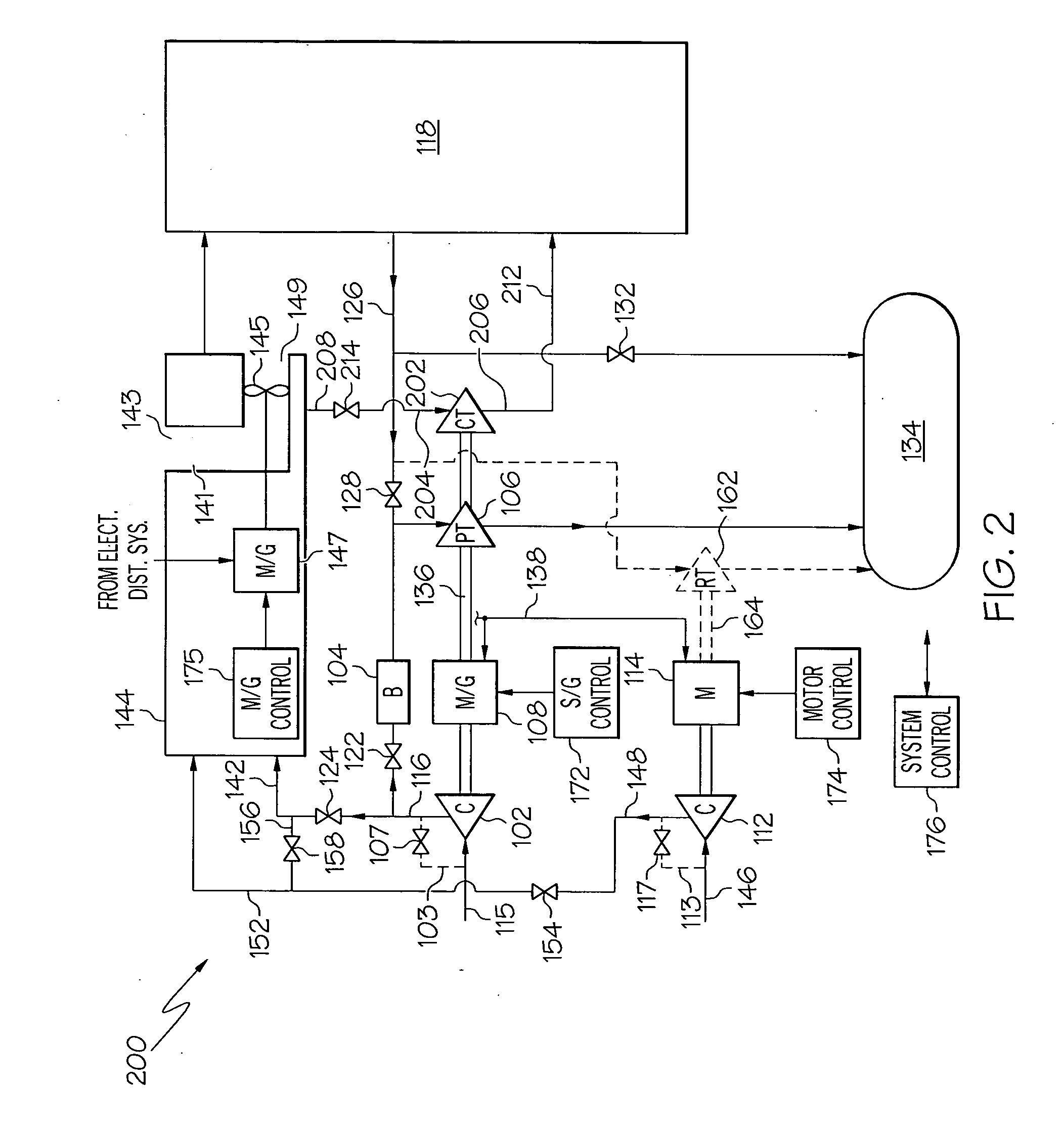
[0017] Turning now to the description, and with reference first to FIG. 1, an embodiment of an exemplary integrated power and pressurization system 100 is shown in simplified schematic form. The system 100 depicted in FIG. 1 includes a first compressor 102, a combustor 104, a power turbine 106, a motor-generator unit 108, a second compressor 112, and a motor 114. It will be appreciated that although the system 100 is depicted as including only the first and second compressors 102, 112, the system 100 could be implemented with more than this number of compressors. For example, the system 100 could include the first compressor 102, the secon...


PUM


Abstract

An integrated power and pressurization management system supplies electrical power and cabin pressurization and cooling air during both airborne and ground operations. The system includes an integral auxiliary power unit (APU) that has a compressor, a motor-generator, and a power turbine all mounted on one shaft. The integral APU can supply compressed air for cabin pressurization and environmental cooling functions, and can generate electrical power for various electrical loads. The system further includes one or more electrically driven compressors.

Description

CROSS-REFERENCES TO RELATED APPLICATIONS [0001] This application claims the benefit of U.S. Provisional Application No. 60 / 603,943, filed Aug. 23, 2004.TECHNICAL FIELD [0002] The present invention relates to electric power and cabin pressurization and, more particularly, to an integrated system that provides both electrical power generation and cabin pressurization functions in an aircraft. BACKGROUND [0003] Electric power generation and cabin pressurization are functions that are implemented on most aircraft. These functions may need to be implemented during normal and abnormal flight conditions, and during aircraft ground operations. In many instances, each of these functions is implemented using separate subsystems and / or devices, which can increase overall system weight and costs. [0004] Aircraft designs are trending toward more electric support platforms. Such design platforms typically implement a “no bleed air” concept, and rely on electrically driven compressors to produce t...

Claims


Application Information

Patent Timeline
Patent Type & Authority Applications(United States)
IPC IPC(8): B64D11/00
CPCB64D13/02B64D13/06Y02T50/56Y02T50/44B64D2013/0611H01M8/04111H01M2250/20Y02E60/50Y02T50/40Y02T50/50Y02T90/40
Inventor DEROUINEAU, JEAN-LUCSCHENK, BJOERNLUI, CLARENCE
Owner HONEYWELL INT INC
Why Eureka
Try Eureka