First stage dual-alloy turbine wheel

a turbine wheel and alloy technology, applied in the direction of machines/engines, reaction engines, mechanical equipment, etc., can solve the problems of high operational temperature and attachment stress, main engine may not be able to supply power, and main engine may not be operating, etc., to achieve high energy air and high energy

Active Publication Date: 2008-12-11
HONEYWELL INT INC
View PDF15 Cites 50 Cited by
  • Summary
  • Abstract
  • Description
  • Claims
  • Application Information

AI Technical Summary

Benefits of technology

[0007]According to one embodiment of the invention, a gas turbine engine is provided that includes an air inlet, a compressor that receives and compresses air from the air inlet, a combustion chamber that receives compressed air from the compressor and combusts fuel to produce high energy air, and a first-stage turbine receiving the high energy air directly from the combustion chamber. The first-stage turbine includes a disk formed from a first alloy, and a unitary blade wheel formed from a second alloy that is different than the first alloy. The unitary blade wheel includes an annular member joined to the disk, and blades that are integrally formed with the annular member.
[0008]According to another embodiment of the invention, a first-stage turbine is provided that is adapted for receiving high energy air directly from a combustion chamber in a gas turbine engine auxiliary power unit. The first-stage turbine includes a disk formed from a first alloy and having an outer surface, and a unitary blade wheel formed from a second alloy that is different than the first alloy. The unitary blade wheel includes an annular member having an inner surface that is joined to the disk, and blades that are integrally formed with the annular member.
[0009]According to yet another embodiment of the invention, a method is provided for manufacturing a first-stage turbine adapted for receiving high energy air directly from a combustion chamber in a gas turbine engine. A powdered first alloy is hot isostatic pressed to form a disk having an outer surface. A unitary blade wheel having an inner surface is also cast from a second alloy that is different than the first alloy. The unitary blade wheel includes an annular member, and blades that are integrally formed with the annular member. The disk and the unitary blade wheel are joined together, and the joined disk and wheel are solution heat treated.

Problems solved by technology

However, when an aircraft is on the ground, its main engines may not be operating.
Moreover, in some instances the main engines may not be capable of supplying power.
Although it is desirable to eliminate the potential for axial shift or walk, to date there has not been a suitable alternative to the inserted blade design that bestows suitable metallurgical properties for the disk and blades.
Also, the high operational temperatures and attachment stresses that are subjected on the turbines require machining the individual blades and slots to tight tolerances.
This involves excessive labor and time.

Method used


Image

  • First stage dual-alloy turbine wheel
  • First stage dual-alloy turbine wheel
  • First stage dual-alloy turbine wheel

Examples


Embodiment Construction

[0017]The following detailed description of the invention is merely exemplary in nature and is not intended to limit the invention or the application and uses of the invention. Furthermore, there is no intention to be bound by any theory presented in the preceding background of the invention or the following detailed description of the invention.

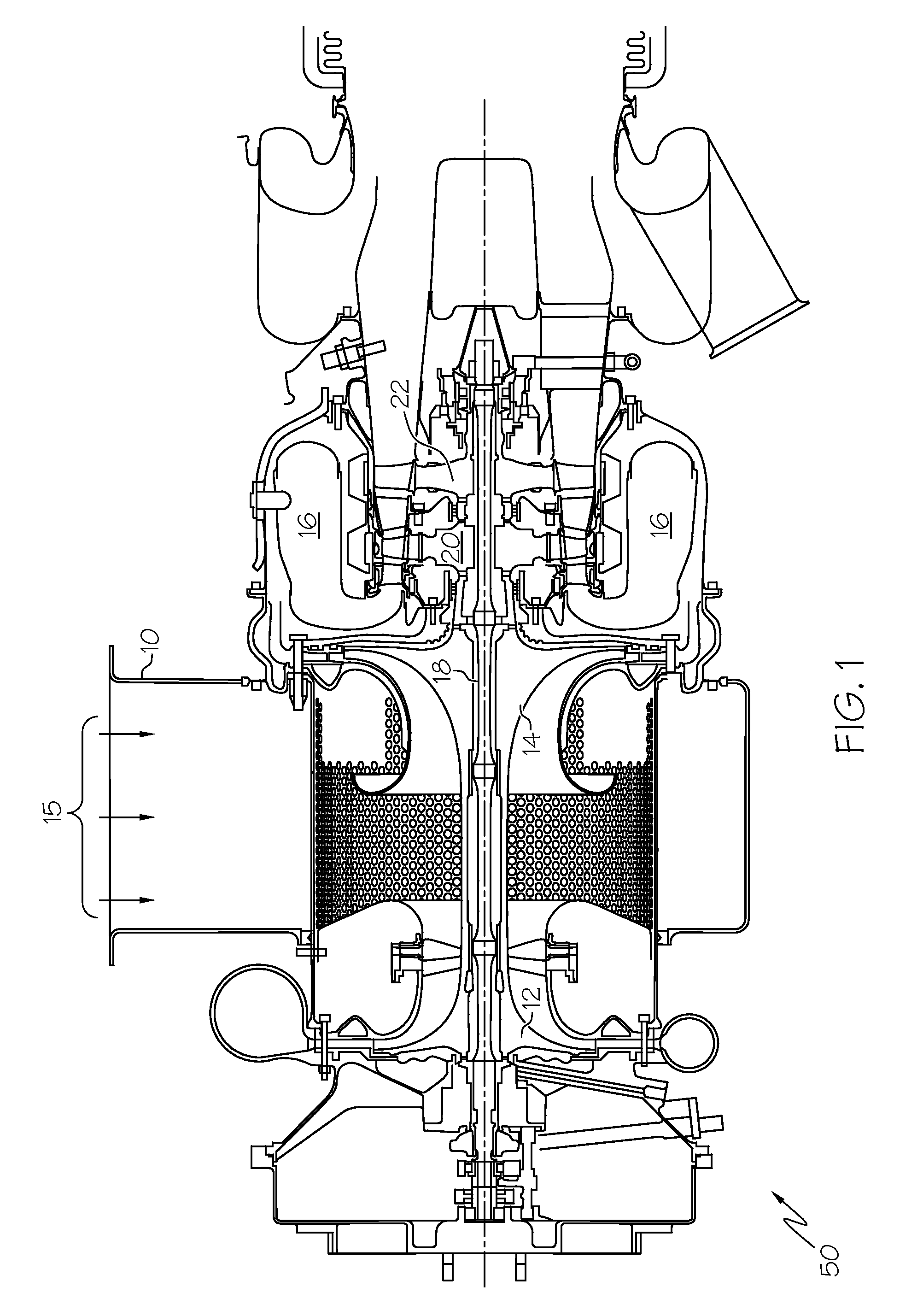
[0018]FIG. 1 is a cross-sectional view of an aircraft APU 50 having a two-stage power turbine assembly according to an embodiment of the invention. During operation of the APU 50, an inlet 10 receives ambient airflow 15, which is then directed to either a load compressor 12 or an engine compressor 14. Both compressors 12 and 14 are rotatably mounted on a shaft 18. The load compressor 12 draws in and compresses air for use as part of an environment control system (ECS) to cool and heat the aircraft interior. The engine compressor 14 draws in and compresses air that will be used to provide auxiliary power. An annular combustor 16 receives fuel...


PUM

PropertyMeasurementUnit
thicknessaaaaaaaaaa
temperatureaaaaaaaaaa

Abstract

A first-stage turbine that is adapted for receiving high energy air directly from a combustion chamber in a gas turbine engine auxiliary power unit includes a disk formed from a first alloy and having an outer surface, and a unitary blade wheel formed from a second alloy that is different than the first alloy. The unitary blade wheel includes an annular member having an inner surface that is joined to the disk, and blades that are integrally formed with the annular member.

Description

FIELD OF THE INVENTION[0001]The present invention relates to all gas turbine engines. More particularly, the present invention relates to the architecture and materials for turbine wheels employed in auxiliary power units and main propulsion engines.BACKGROUND OF THE INVENTION[0002]Aircraft main engines not only provide propulsion for the aircraft, but in many instances are used to drive various other rotating components such as, for example, generators, compressors, and pumps, to thereby supply electrical, pneumatic, and / or hydraulic power. However, when an aircraft is on the ground, its main engines may not be operating. Moreover, in some instances the main engines may not be capable of supplying power. Thus, many aircraft include one or more auxiliary power units (APUs) to supplement the main propulsion engines in providing electrical and / or pneumatic power. An APU may additionally be used to start the main propulsion engines.[0003]An APU is, in most instances, a gas turbine engi...

Claims


Application Information

Patent Timeline
Patent Type & Authority Applications(United States)
IPC IPC(8): F01D5/14
CPCF01D5/02F01D5/30F01D5/34F05D2230/21Y10T29/49316F05D2230/40F05D2230/10F05D2230/314F05D2230/23
Inventor MARSHALL, SCOTT J.REYES, VICTOR M.O'BRIEN, TIMOTHY R.TRAN, HUYSZUROMI, ANDREW F.
Owner HONEYWELL INT INC
Why Eureka
Try Eureka