Method and system for a transmitting mobility state
a technology of mobility state and transmission method, applied in the field of wireless cellular communication technology, can solve problems such as problems to be solved, and achieve the effects of reducing unnecessary handovers, improving handover success rate, and maintaining user service continuity
- Summary
- Abstract
- Description
- Claims
- Application Information
AI Technical Summary
Benefits of technology
Problems solved by technology
Method used
Image
Examples
first embodiment
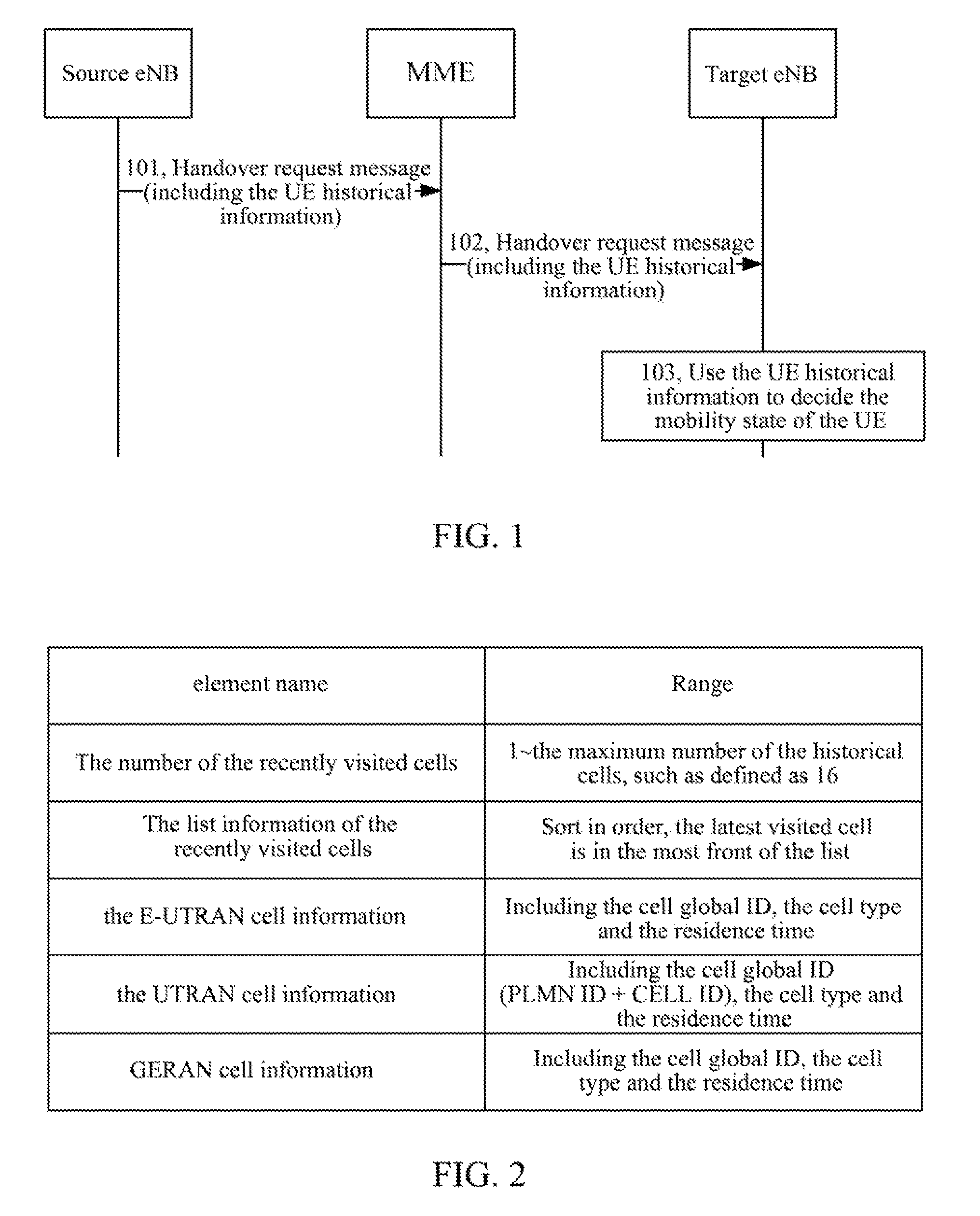
[0075]For the S1 handover, the specific method for transmitting a mobility state is shown as the first embodiment shown in FIG. 1, mainly comprising the following steps:
[0076]step 101, the source eNB sends a handover request message to the MME, the message contains the UE historical information.
[0077]the structure of the UE historical information is shown as FIG. 2, comprising: the information of the historical cells in which the UE was located before it hands over to the target cell, the information only includes the historical information record in one connectivity state, specifically comprising the number of the cells recently visited by the UE and the list information of the cells recently visited by the UE; the UE historical information also comprises: the E-UTRAN cell information, the UTRAN cell information and the global system for mobile communications (GSM) / Enhanced Data Rate for GSM Evolution (EDGE) Radio Access Network (GERAN) cell information. The E-UTRAN cell informatio...
second embodiment
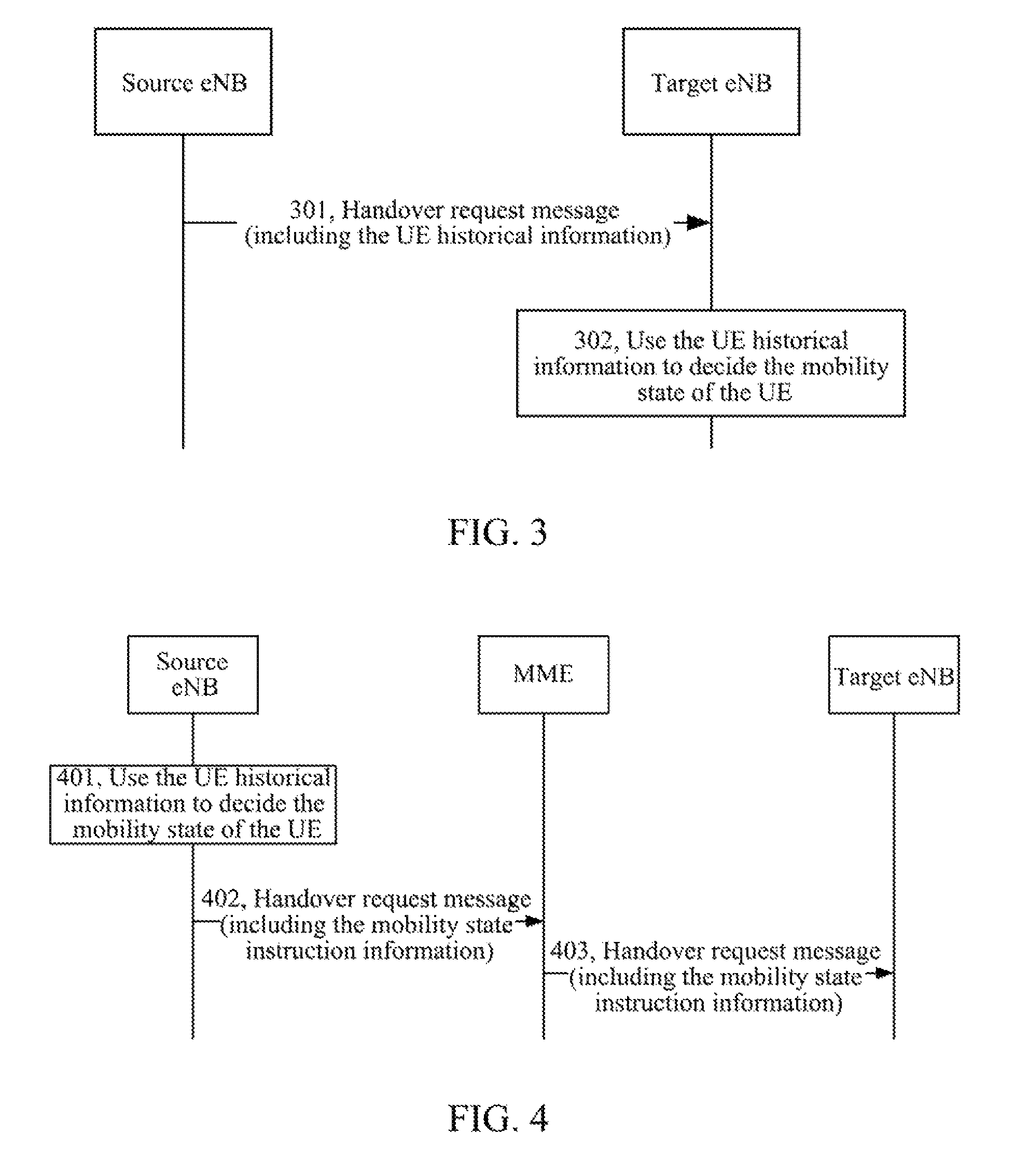
[0086]For the X2 handover, the specific method for transmitting a mobility state is shown as the second embodiment in FIG. 3, mainly comprising the following steps:
[0087]step 301, the source eNB directly sends a handover request message to the target eNB, and the message contains the UE historical information.
[0088]Step 302, the target eNB extracts the UE historical information from the received handover request message, and decides the mobility state of the UE based on the UE historical information.
[0089]the specific operation of deciding the mobility state of the UE is the same as that in the first embodiment shown in FIG. 1 and is not repeated here.
[0090]To achieve the method for transmitting a mobility state in the aforementioned first and second embodiments, the present invention also provides a system for transmitting a mobile state, comprising: a source eNB and a target eNB. The source eNB is used to send the UE historical information to the target eNB when performing a hando...
third embodiment
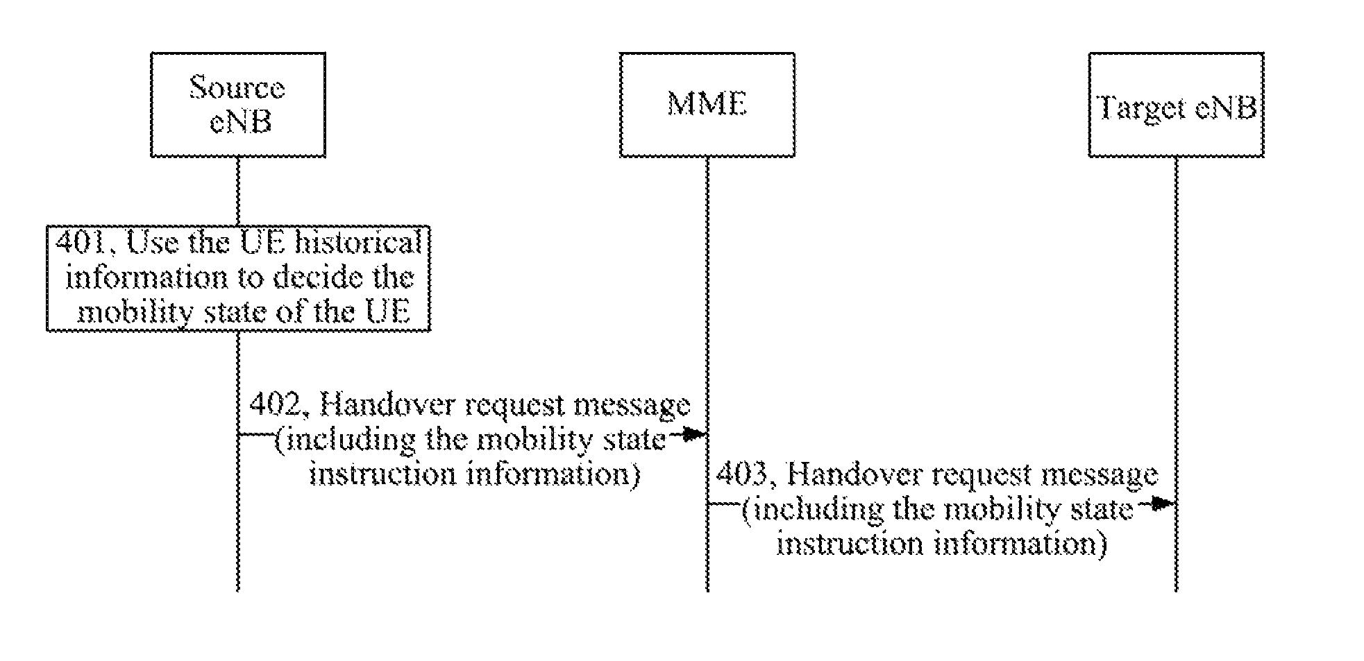
[0094]For the S1 handover, the specific method for transmitting a mobility state is shown as the third embodiment shown in FIG. 4, mainly comprising the following steps:
[0095]step 401, the source eNB decides the mobility state of the UE that currently needs to hand over according to the UE historical information when performing a handover of the UE in the connectivity state.
[0096]the specific operation of deciding the mobility state of the UE is the same as that in the first embodiment shown in FIG. 1 and is not repeated here.
[0097]Step 402, the source eNB constructs a handover request message, adds the UE mobility state instruction information into the message, and sends the handover request message carrying the UE mobility state instruction information to the MME.
[0098]The handover request message is the enumeration type, including the normal mobility state, the medium-speed mobility state and the high-speed mobility state. The UE mobility state instruction information is set base...
PUM
 Abstract
Description
Claims
Application Information
 - R&D
- Intellectual Property
- Life Sciences
- Materials
- Tech Scout
- Unparalleled Data Quality
- Higher Quality Content
- 60% Fewer Hallucinations
Browse by: Latest US Patents, China's latest patents, Technical Efficacy Thesaurus, Application Domain, Technology Topic, Popular Technical Reports.
© 2025 PatSnap. All rights reserved.Legal|Privacy policy|Modern Slavery Act Transparency Statement|Sitemap|About US| Contact US: help@patsnap.com


