
Knee brace

a knee brace and knee technology, applied in the field of knee braces, can solve the problems of high level, abnormal motion, and common injury to the knee, and achieve the effect of easy support for the kn

Inactive Publication Date: 2014-04-08
FOX RICHARD
View PDF17 Cites 2 Cited by
  • Summary
  • Abstract
  • Description
  • Claims
  • Application Information

AI Technical Summary

Benefits of technology

The present invention provides a knee brace that allows easy support of the user's knee without the need for extra tape or rigid metal / composite bars. The brace can be strapped in a way that mimics the technique used by professionals like chiropractors and trainers.

Problems solved by technology

Additionally, the knee is also a common subject of injury due to the relatively high levels of stress it bears under dynamic loads that are often multiples of the entire weight of the body and due to its flexibility placing it in vulnerable positions.
During many activities, the knee can undergo abnormal motions as a result of quick changes in direction, fatigue, uneven surfaces, or impact which can cause sprains or more serious injuries, such as dislocation or stretching or tearing of the tissues that make up the knee or fractures of the bones of and proximate the knee.
Specifically, injuries to the knee may occur from muscular imbalances, and in particular the imbalance of two of the quadriceps muscle group: the Vastus medialis oblique (VMO) muscle located on the inner aspect of the thigh and the Vastus lateralis located on the outer aspect of the thigh.
While simple sleeve-based braces offer some protection and stability to the knee, they are often insufficient for high impact activities such as football, skiing or competitive roller skating (“roller derby”).
However, such rigid members are often relatively heavy and cumbersome and do not permit normal knee flexibility.
Additionally, such rigid members may not be permitted to be worn during contact sports or activities, such as football and roller derby, because the rigid member may injure another competitor.

Method used


Image

  • Knee brace
  • Knee brace
  • Knee brace

Examples


Embodiment Construction

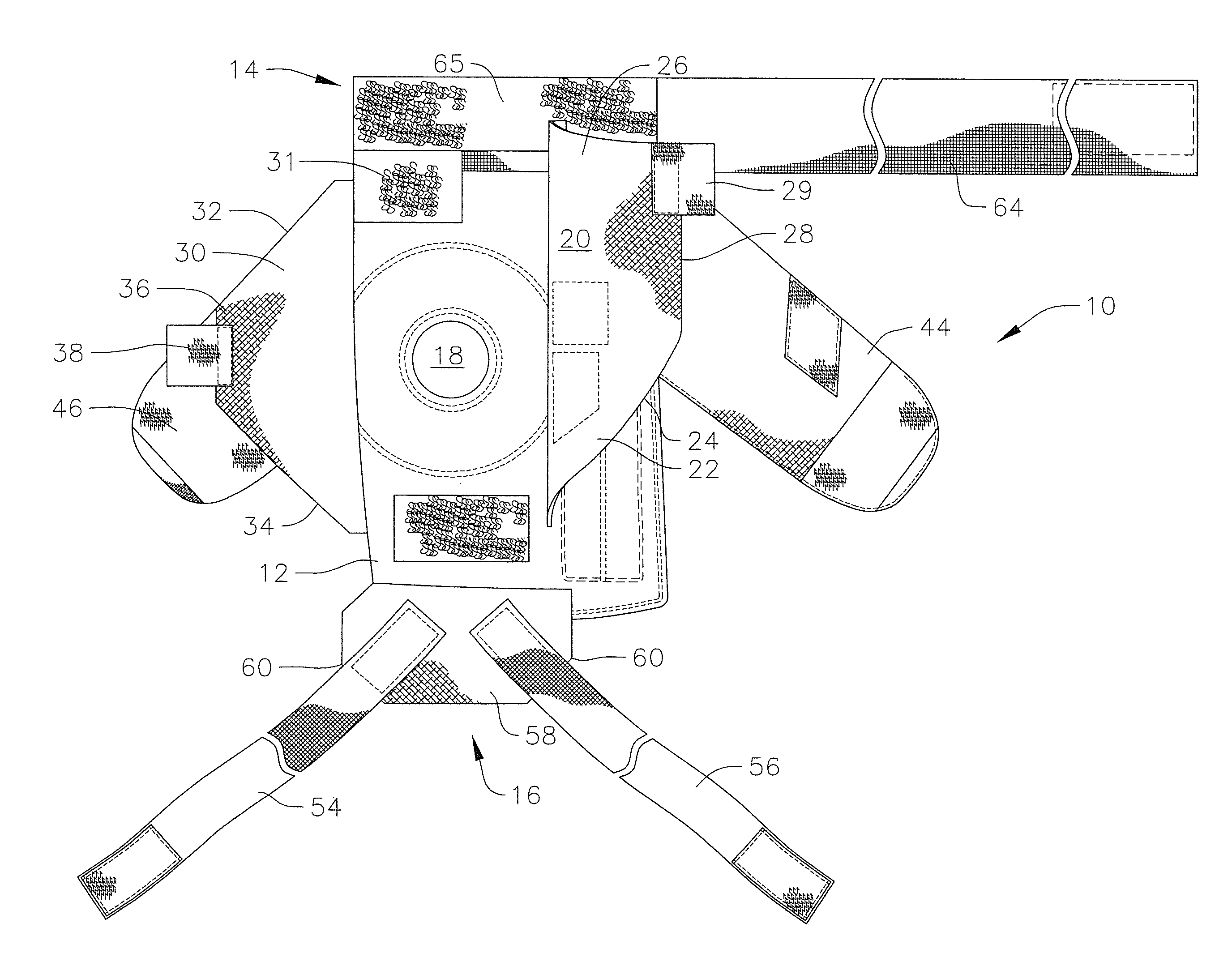
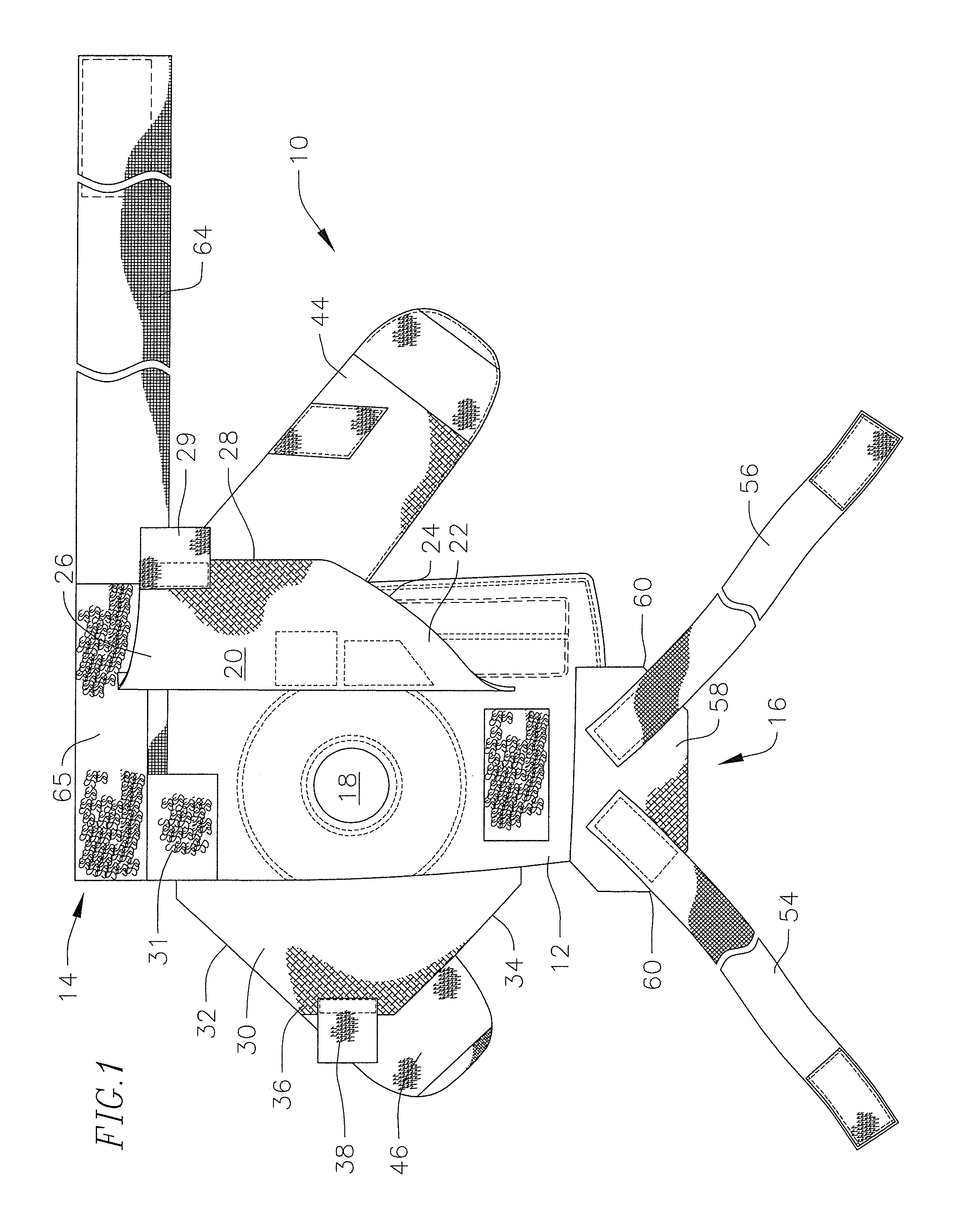
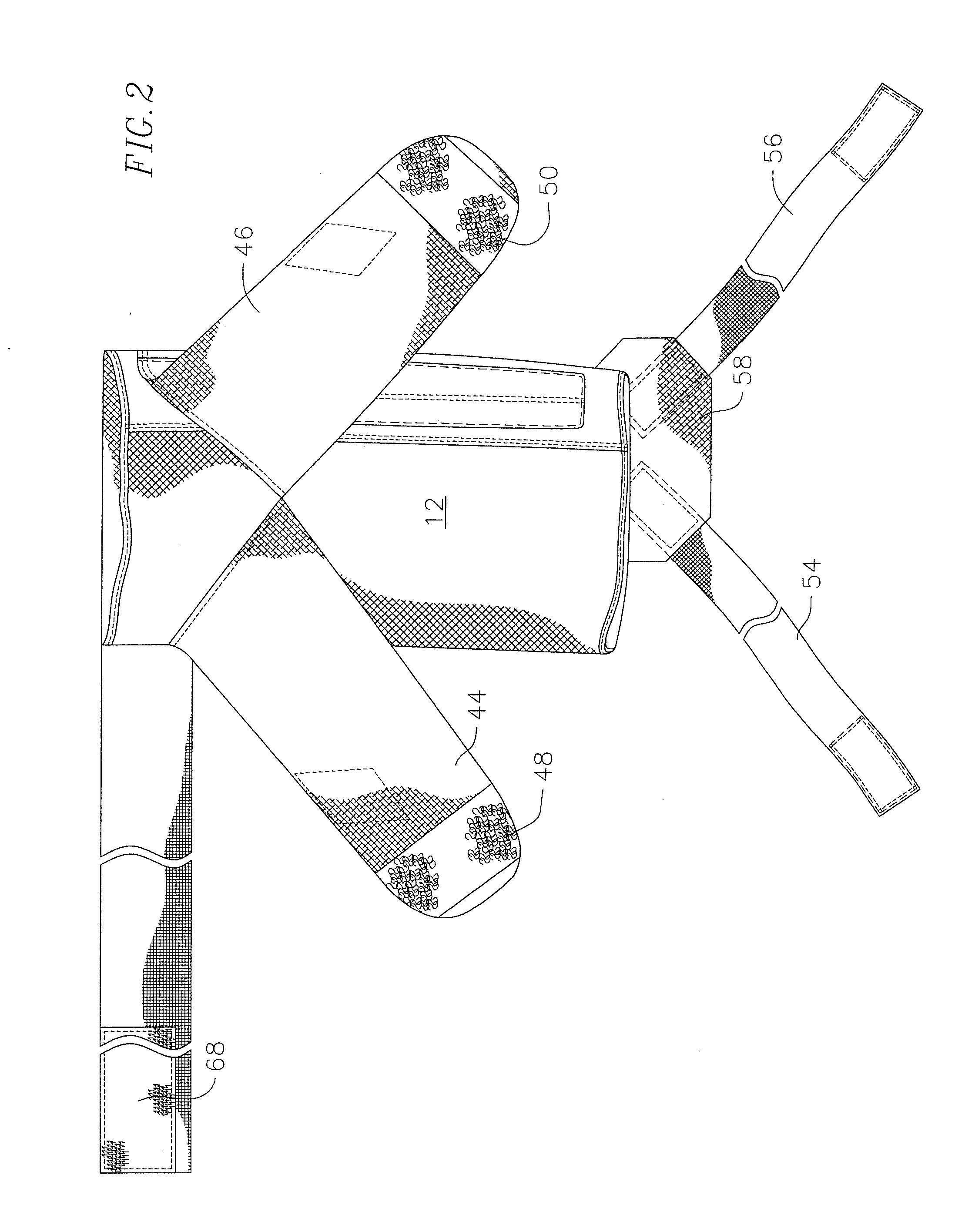
[0019]Embodiments of the present invention are generally directed to a knee brace having a flap and strap configuration for supporting a wearer's knee without encumbering the wearer or without significantly restricting her range of movement. As described in more detail below, the knee brace configuration resembles a support structure that can be provided by athletic tape, but further provides impact protection for the knee and does not require a skilled and trained athletic trainer to be applied.

[0020]With reference now to FIGS. 1 and 2, an embodiment of a knee brace 10 includes a sleeve 12 that serves generally as a base for the knee brace. The sleeve 12 has an open top end 14 and an open bottom end 16 that allows it to slide over a wearer's leg up to around her knee area. The sleeve 12 may be made from a relatively flexible material that is also stretchable, thereby allowing it to fit tightly around the wearer's lower thigh, knee, and upper shin and provide support thereto. For ex...


PUM


Abstract

A knee brace includes a sleeve; and a plurality of flaps including a first lateral flap coupled to a first side of the sleeve and configured to extend toward a center of the sleeve; a second lateral flap coupled to a second side of the sleeve substantially opposite to the first side and configured to extend toward a center of the sleeve and overlap with the first transverse flap; a first transverse flap and a second transverse flap coupled to a rear side of the sleeve and configured to wrap around the first side and the second side of the sleeve, respectively, and overlap the first and second lateral flaps. Additionally, the knee brace may include a lower flap as an anterior cruciate ligament support and first and second transverse straps configured to extend over the plurality of flaps.

Description

BACKGROUND[0001]1. Field[0002]Embodiments of the present invention generally relate to a knee brace.[0003]2. Discussion or Related Art[0004]Knee braces are often used by athletes and other persons engaged in physical activity to protect the knee from injury or to avoid exacerbation of an existing injury. The knee is one of the most heavily worked joints of the human body because it is used in any activity that involves movement of the leg, including, for example, running, walking, skiing, surfing, roller skating snowboarding and skateboarding. Additionally, the knee is also a common subject of injury due to the relatively high levels of stress it bears under dynamic loads that are often multiples of the entire weight of the body and due to its flexibility placing it in vulnerable positions. During many activities, the knee can undergo abnormal motions as a result of quick changes in direction, fatigue, uneven surfaces, or impact which can cause sprains or more serious injuries, such...

Claims


Application Information

Patent Timeline
Patent Type & Authority Patents(United States)
IPC IPC(8): A61F5/00
CPCA61F5/0111
Inventor FOX, RICHARD
Owner FOX RICHARD
Learn More