
Articulating injection cannula and seal assembly

a technology of articulating injection and seal assembly, which is applied in the field of spinal system and method treatment, can solve the problems of uncontrolled leakage, affecting the treatment effect, and causing the potential for the prosthetic fluid to ooze or seep out of the disc spa

Inactive Publication Date: 2014-04-08
SPINEWAVE
View PDF26 Cites 12 Cited by
  • Summary
  • Abstract
  • Description
  • Claims
  • Application Information

AI Technical Summary

Benefits of technology

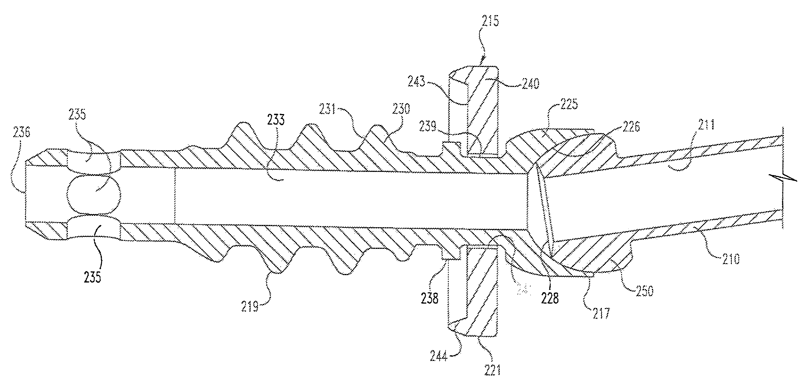
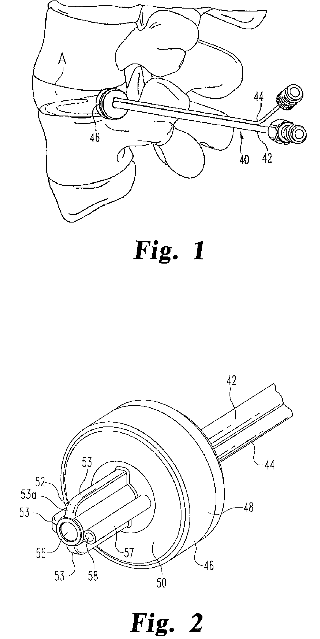
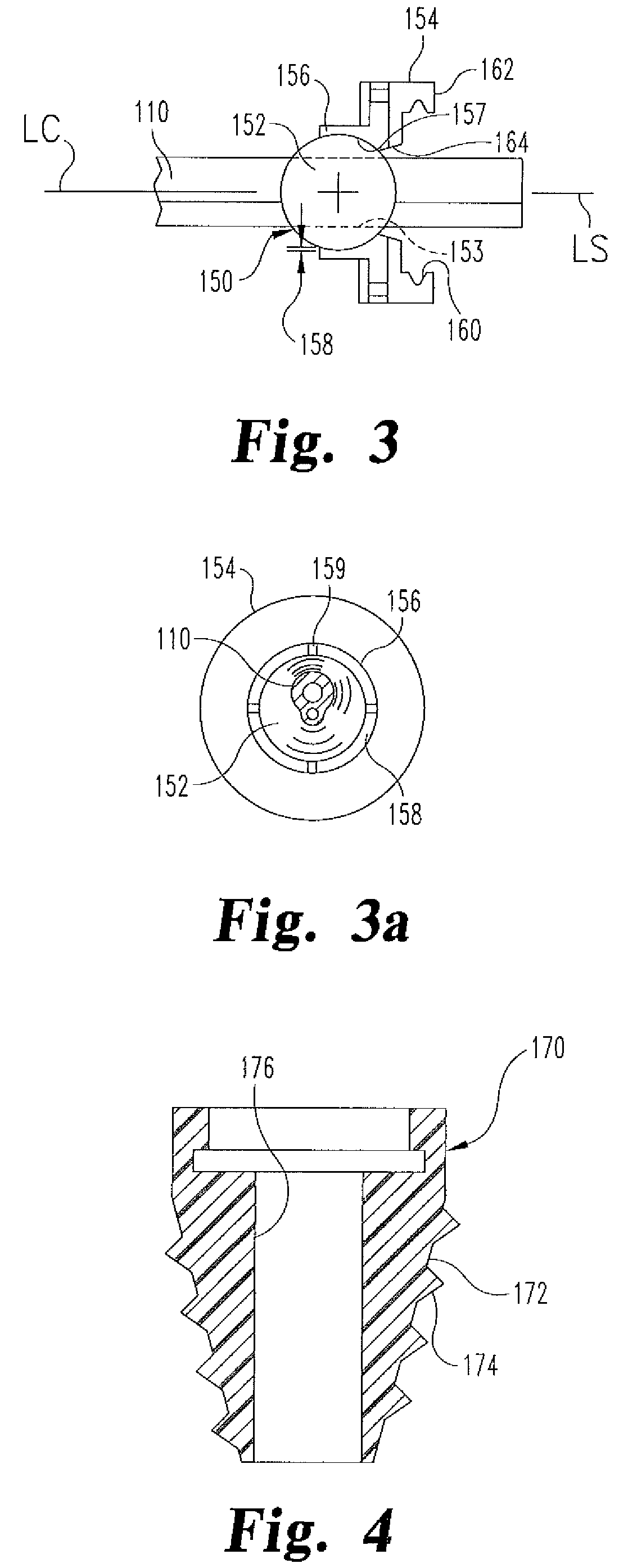
[0007]In one aspect of the invention, an assembly is provided for sealably injecting a fluent material into an intradiscal space accessed through an opening in the annulus of a spinal disc. The assembly comprises a cannula having a passageway for injecting the fluent material therethrough into the intradiscal space, a seal having a sealing surface for sealing engagement with the outer surface of the disc annulus and defining a central opening, and an articulating joint defined between the central opening of the seal and the cannula configured to permit relative articulation therebetween. In certain embodiments, the articulating joint is a ball and socket joint to permit spherical articulation of the cannula relative to the seal, and therefore relative to the disc annulus. This articulation capability allows the surgeon to optimally position the cannula for injecting the fluent material while the seal is engaged to the annulus.
[0009]In another feature, the assembly further comprises an anchor element extending through the central opening of the seal. The anchor element includes an elongated body sized for sealing engagement within the opening in the disc annulus and defining a bore for injecting the fluent material therethrough into the intradiscal space. The anchor element thus anchors the seal against the annulus as the fluent material is introduced through the cannula. The anchor element may define an annular recess at a proximal end thereof, while the central opening in the seal is sized to fit within the annular recess. In certain embodiments, the elongated body of the anchor element is threaded so that the anchor element may be threaded into the opening in the disc annulus. In these embodiments, the central opening of the seal is configured to permit relative rotation between the anchor element and the seal when the seal is engaged within the annular recess. The seal may also be sized to permit some axial play within the annular recess. With this feature, as the anchor element is threaded into the annulus, the anchor element will exert pressure against the seal to not only seal the central opening but also to enhance the sealing engagement of the sealing surface to the surface of the annulus.
[0012]Certain embodiments of the present invention thus provides an assembly for sealably injecting a fluent material into an intradiscal space that permits relative angulation between an introducer cannula and the disc annulus. Other embodiments provide an assembly for sealably injecting the fluent material in which a seal is anchored to the disc annulus. In yet other embodiments, the articulation and anchoring features are combined into an assembly that ensures fluid-tight introduction of a fluent material into a disc space.

Problems solved by technology

Problems associated with these devices occur during insertion, whereby the pressure required to fill the disc space can cause leakage of the material into sensitive adjacent areas.
Much of the prior art devices and methods contemplate free injection of biomaterial into a spinal space which may lead to uncontrolled leakage.
Lastly, some methods require insertion under high pressure, thereby creating a potential for the prosthetic fluid to ooze or seep out of the disc space intra-operatively.

Method used


Image

  • Articulating injection cannula and seal assembly
  • Articulating injection cannula and seal assembly
  • Articulating injection cannula and seal assembly

Examples


Embodiment Construction

[0024]For the purposes of promoting an understanding of the principles of the invention, reference will now be made to the embodiments illustrated in the drawings and described in the following written specification. It is understood that no limitation to the scope of the invention is thereby intended. It is further understood that the present invention includes any alterations and modifications to the illustrated embodiments and includes further applications of the principles of the invention as would normally occur to one skilled in the art to which this invention pertains.

[0025]In a particular procedure that may incorporate the present invention, an injectable nucleus is surgically introduced into the spine as a replacement for or augment to the natural nucleus pulposus. The injectable nucleus is preferably a curable biocompatible polymer with properties that emulate those of the natural human disc. A suitable injectable nucleus material is disclosed in U.S. Pat. Nos. 6,423,333; ...


PUM


Abstract

An assembly for sealably injecting a fluent material into an intradiscal space accessed through an opening in the annulus of a spinal disc comprises a cannula having a passageway for injecting the fluent material therethrough into the intradiscal space, a seal having a sealing surface for sealing engagement with the outer surface of the disc annulus and defining a central opening for, and an articulating joint defined between the central opening of the seal and the cannula configured to permit relative articulation between the components. The assembly may further comprise an anchor element extending through the central opening of the seal, the anchor element including an elongated threaded body sized for threaded engagement within the opening in the disc annulus and having a head configured to engage a distal end of the cannula.

Description

RELATED APPLICATIONS[0001]This application claims priority to provisional application No. 60 / 883,472, which was filed on Jan. 4, 2007, and is a continuation-in-part of each of applications Ser. No. 11 / 170,010 now U.S. Pat. No. 7,722,579; Ser. No. 11 / 170,577 now U.S. Pat. No. 7,789,913; Ser. No. 11 / 170,382 now U.S. Pat. No. 7,556,650; Ser. No. 11 / 169,405 now U.S. Pat. No. 7,740,660; Ser. No. 11 / 170,588 now U.S. Pat. No. 7,837,733 and Ser. No. 11 / 170,657 now U.S. Pat. No. 8,337,557, all filed on Jun. 29, 2005, all of which claim priority to provisional application No. 60 / 683,665, filed on Jun. 29, 2004, as well as to provisional application No. 60 / 843,256, filed on Sep. 28, 2006. The disclosure of each of these applications is incorporated herein by reference.BACKGROUND OF THE INVENTION[0002]The present invention relates to systems and methods for the treatment of the spine, and especially the interbody disc space. More specifically, the invention concerns the injection of a biomateri...

Claims


Application Information

Patent Timeline
Patent Type & Authority Patents(United States)
IPC IPC(8): A61M5/178A61F2/00A61M5/00A61B17/58A61B17/60
CPCA61F2002/444A61F2002/4627A61F2002/4628A61F2/4611A61F2002/4663A61F2/4657A61F2/4684A61B17/8811A61B17/8816
Inventor COLLINS, KEITHWILSON, THOMAS G.RAYMOND, SPANKY A.
Owner SPINEWAVE
Learn More