Printer

a printing machine and printing plate technology, applied in the field of printing machines, can solve the problems of increasing the cost of the apparatus, reducing the feeding force, damage to the protective film, etc., and achieve the effect of reducing the pressing for

Active Publication Date: 2014-04-08
SEIKO INSTR INC
View PDF4 Cites 2 Cited by
  • Summary
  • Abstract
  • Description
  • Claims
  • Application Information

AI Technical Summary

Benefits of technology

[0011]Therefore, the present invention has been made in view of such circumstances, and provides a printer capable of handling a plurality of roll sheets each having a different width in the same apparatus while actively reducing the pressing force to be imparted to the region in which the thermal head and the platen roller are brought into direct contact with each other.

Problems solved by technology

In the contact region, abrasion between the thermal head and the platen roller may cause a reduction of a feeding force due to a worn surface of the platen roller, damage of a protective film on the surface of the thermal head, and the like.
However, this configuration leads to a problem of an increase in cost of the apparatus.
However, the above-mentioned configuration of JP 2007-168350 A has a problem that, in a case of using the second roll sheet, the pressing force imparted to the contact region between the thermal head and the platen roller cannot be reduced yet fully.

Method used


Image

  • Printer
  • Printer
  • Printer

Examples


Embodiment Construction

Thermal Printer

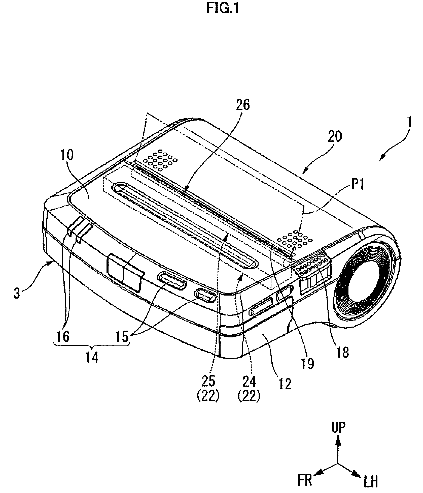
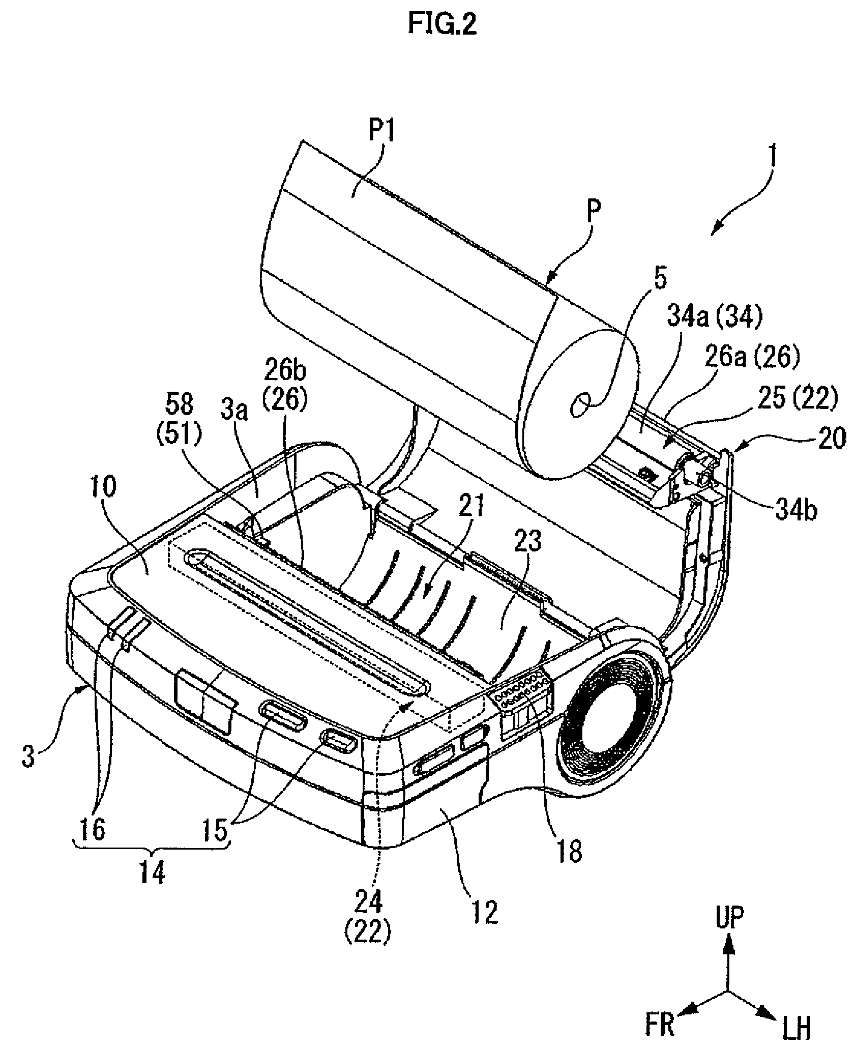
[0034]Next, embodiments of the present invention are described with reference to the drawings. FIG. 1 is a perspective view illustrating a state in which a paper cover of a thermal printer is at a closed position, and FIG. 2 is a perspective view illustrating a state in which the paper cover is at an open position. Note that, in the following description, for easy understanding of the invention, illustrations are simplified, as appropriate, by omitting a part of a component, simplifying a shape, changing a contraction scale, etc. Further, in the drawings, FR, LH, and UP represent a front side, a left side, and an upper side of the printer, respectively.

[0035]As illustrated in FIGS. 1 and 2, a thermal printer (printer) 1 is configured to be capable of performing printing on a plurality of kinds of thermal papers P1 each having a different width. The thermal paper P1 is a heat sensitive sheet which undergoes a color change when heat is applied thereto, and the thermal p...


PUM


Abstract

A printer performs printing on a thermal paper drawn from roll sheets having different widths. The printer has a thermal head and a platen roller arranged opposite to the thermal head and mounted to undergo rotation for sending out the thermal paper in a state of sandwiching the thermal paper between the thermal head and the platen roller. Elastic members are arrayed along the width direction of the thermal paper and are provided on an opposite side of the platen roller with respect to the thermal head for pressing the thermal head toward the platen roller. Only one of the elastic members is provided with a pressing force releasing mechanism for separating the one elastic member from the thermal head according to a width of the one roll sheet from which the thermal paper is drawn and for releasing pressing of the thermal head by the one elastic member.

Description

BACKGROUND OF THE INVENTION[0001]1. Field of the Invention[0002]The present invention relates to a printer for performing printing of various types of information on a thermal paper drawn from a roll sheet.[0003]2. Description of the Related Art[0004]A large number of thermal printers of various types are presently provided in which printing is performed by pressing a thermal head against a special thermal paper (heat sensitive sheet) which undergoes a color change when heat is applied thereto. In particular, the thermal printer is suitably used in printing a variety of labels, receipts, and tickets because it is possible to perform the printing of smooth letters and various graphics without using toners, inks, or the like.[0005]The above-mentioned thermal printer performs printing by sandwiching a thermal paper between a platen roller and a thermal head, and by heating a printing surface (heat sensitive surface) of the thermal paper by heating elements of the thermal head while fee...

Claims


Application Information

Patent Timeline
Patent Type & Authority Patents(United States)
IPC IPC(8): B41J2/32
CPCB41J25/312B41J11/0025
Inventor JIMBO, TAKASHI
Owner SEIKO INSTR INC
Why Eureka
Try Eureka