Laser sensor system based on self-mixing interference
a laser sensor and interference technology, applied in the direction of reradiation, distance measurement, instruments, etc., can solve the problem of laser light modulation, achieve the effect of improving the signal-to-noise ratio of detected modulation, preventing non-linearities, and increasing the detection range of sensor modules
- Summary
- Abstract
- Description
- Claims
- Application Information
AI Technical Summary
Benefits of technology
Problems solved by technology
Method used
Image
Examples
first embodiment
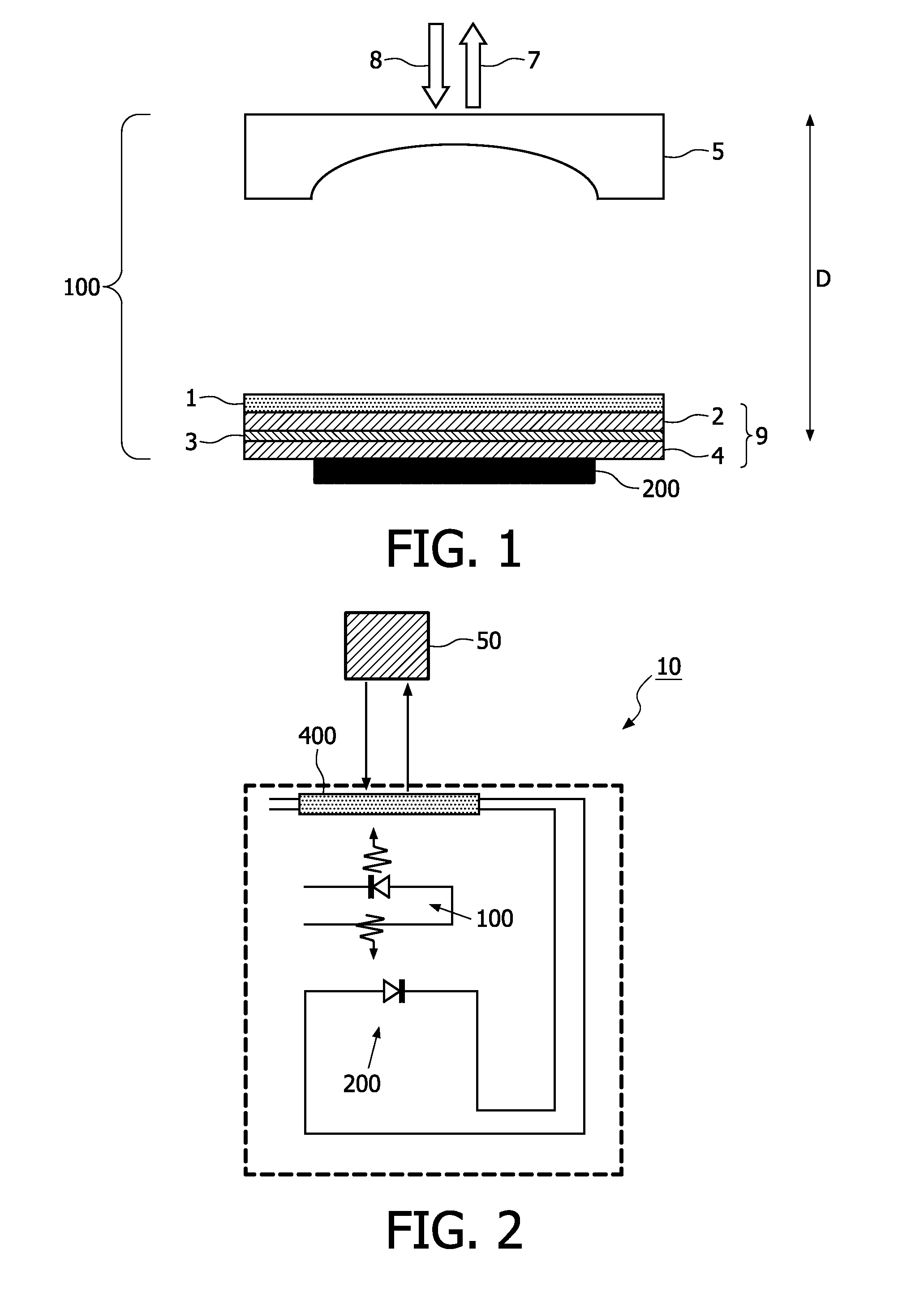
[0035]FIG. 2 shows a schematic view of a sensor module 10 according to the current invention. A laser source 100 in this case a VCSEL is connected to a driving circuit (not shown) and a power source (not shown). The laser light emitted by the VCSEL passes a control element 400 comprising a lens with variable focus and control circuitry both being also connected to the power source (not shown). After passing the lens with variable focus the laser light hits the target 50 and a part of the laser light is reflected by the target 50, passes the autofocus lens again and reentes the laser cavity of the VCSEL causing a modulation of the laser light in the laser cavity. The modulation of the laser light in the laser cavity is detected by a detector 200 being a photodiode attached to the VCSEL as discussed above. The electrical signal being generated by means of the photodiode due to the modulation of the laser light in the laser cavity comprises the information to determine e.g. the velocit...
second embodiment
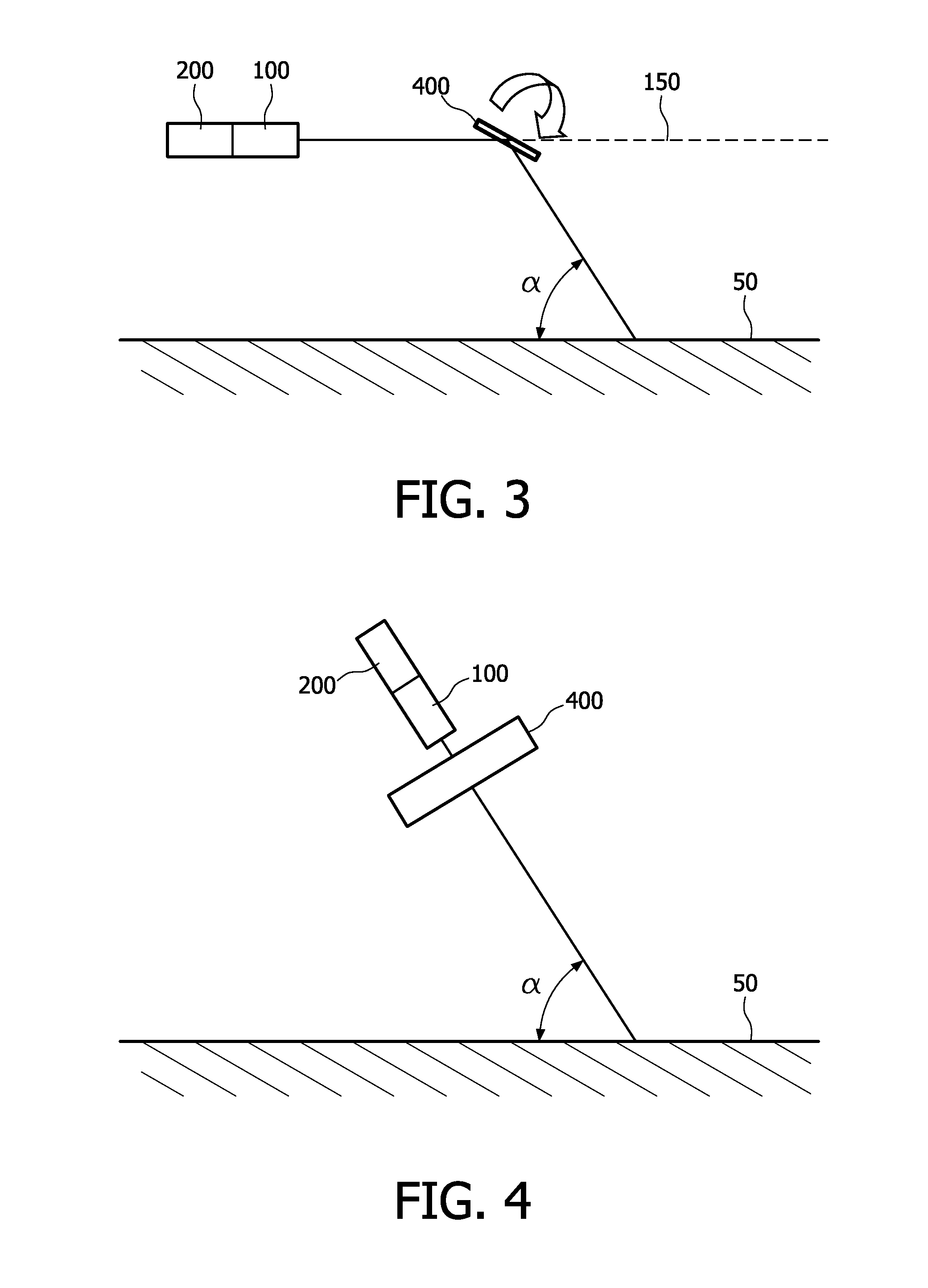
[0036]A schematic view of a sensor module according to the current invention is depicted in FIG. 3. The laser source 100 being attached to a detector 200 emitts laser light that may be focused by means of a lens (not shown). The laser light emitted by the laser source 100 hits the control element 400, whereby the control element 400 comprises a controllable mirror, control circuitry (not shown) and a motor (not shown) to slant the mirror as indicated by the arrow in FIG. 3 with respect to the reference axis 150 defined by the laser light emitted by the laser source 100 before hitting the controllable mirror. Depending on the slanting angle of the controllable mirror with respect to the reference axis 150 the angle of incident a between the laser light deflected by the controllable mirror and the surface of the target 50 changes. The deflected laser light is at least partly reflected by means of the target 50, again deflected by the controllable mirror and reenters the laser cavity o...
third embodiment
[0037]In FIG. 4 a schematic view of a sensor module according to the current invention is shown. The laser source 100 being attached to a detector 200 emits laser light that may be focused by means of a lens (not shown). The laser light emitted by the laser source 100 hits the control element 400, whereby the control element 400 comprises a controllable optical attenuator and control circuitry (not shown). The laser light is at least partly reflected by means of a target 50, passes again the controllable optical attenuator and reenters the laser cavity of the laser source 100 causing a modulation of the laser light in the laser cavity being detected by the detector 200. A computing unit (not shown) may be connected to the detector 200 evaluating the electronic signal provided by the detector 200. The controllable optical attenuator may be used to optimize the signal to noise ratio of the sensor module by controlling the amount of laser light reentering the laser cavity. The control ...
PUM
 Abstract
Description
Claims
Application Information
 - R&D
- Intellectual Property
- Life Sciences
- Materials
- Tech Scout
- Unparalleled Data Quality
- Higher Quality Content
- 60% Fewer Hallucinations
Browse by: Latest US Patents, China's latest patents, Technical Efficacy Thesaurus, Application Domain, Technology Topic, Popular Technical Reports.
© 2025 PatSnap. All rights reserved.Legal|Privacy policy|Modern Slavery Act Transparency Statement|Sitemap|About US| Contact US: help@patsnap.com


