Variable magnification optical system for projection and projection-type display apparatus

a technology of optical system and magnification ratio, which is applied in the field of variable magnification optical system for projection and a zoom lens for projection, can solve the problems of difficult to provide a compact lens system, unsuitable, and inability to obtain sufficient back focus, so as to suppress aberration fluctuations, increase the projection angle, and large the effect of magnification ratio

Inactive Publication Date: 2014-04-08
FUJIFILM CORP
View PDF9 Cites 4 Cited by
  • Summary
  • Abstract
  • Description
  • Claims
  • Application Information

AI Technical Summary

Benefits of technology

[0115]A variable magnification optical system for projection according to a second aspect of the present invention can achieve advantageous effects similar to those of the variable magnification optical system for projection according to the first aspect of the present invention. In this variable magnification optical system for projection, the formula (12) is satisfied instead of the formula (11). Therefore, it is possible prevent the outer diameter of at least one magnification-side lens from becoming large. Hence, it is possible to increase the projection angle of the variable magnification optical system.
[0116]As described above, in the variable magnification optical systems for projection according to the first and second aspects of the present invention, two of four lens groups are movable, and the number of the movable lens groups is small. Further, the variable magnification optical systems for projection have appropriate back focus, and the outer diameter of at least one magnification-side lens does not become too large even when a projection angle is increased. Therefore, it is possible to easily increase the projection angle. Further, it is possible to suppress the fluctuation of aberrations when magnification of the variable magnification optical system is changed, while a large magnification ratio is maintained.
[0117]The variable magnification optical systems for projection according to the first and second aspects of the present invention may be zoom lenses for projection. A zoom lens for projection according to an aspect of the present invention is composed of a first lens group having negative refractive power, a second lens group having negative refractive power, a third lens group having positive refractive power, and a fourth lens group having positive refractive power, which are arranged from the magnification side of the zoom lens in the order mentioned above. Therefore, the outer diameter of at least one magnification-side lens is not too large even when the projection angle of the zoom lens is increased. Further, it is possible to suppress the fluctuation of aberrations when magnification of the variable magnification optical system is changed, while a large magnification ratio is maintained.
[0118]When the zoom lens for projection satisfies the formula (11), appropriate back focus is obtained.
[0119]A zoom lens for projection according to another aspect of the present invention can achieve advantageous effects similar to those of the aforementioned zoom lens for projection. In this zoom lens for projection, the formula (12) is satisfied instead of the formula (11). Therefore, it is possible prevent the outer diameter of at least one magnification-side lens from becoming large. Hence, it is possible to increase the projection angle of the variable magnification optical system.
[0120]As described above, in the zoom lenses for projection according to the present invention, two of four lens groups are movable, and the number of the movable lens groups is small. Further, the zoom lenses for projection have appropriate back focus, and the outer diameter of at least one magnification-side lens does not become too large even when a projection angle is increased. Therefore, it is possible to easily increase the projection angle. Further, it is possible to suppress the fluctuation of aberrations when magnification of the variable magnification optical system is changed, while a large magnification ratio is maintained.

Problems solved by technology

However, when the cost of a lens is considered, it is not desirable to prepare a lens for each movie theater.
However, when the projection angle of the zoom lens for projection is increased without lowering the zoom ratio of the zoom lens, it is impossible to obtain sufficient back focus, or the outer diameter of at least one lens in the first lens group on the magnification side of the zoom lens becomes too large, and it becomes difficult to provide a compact lens system.
Therefore, when the magnification ratio becomes large, the fluctuation of aberration becomes too large.
Hence, it is difficult to substantially increase the magnification ratio.
Therefore, when the magnification of the variable magnification optical system is changed, the numerical aperture fluctuates, and such zoom lenses for projection are not appropriate for movie theaters.

Method used


Image

  • Variable magnification optical system for projection and projection-type display apparatus
  • Variable magnification optical system for projection and projection-type display apparatus
  • Variable magnification optical system for projection and projection-type display apparatus

Examples


first embodiment

Zoom Lens

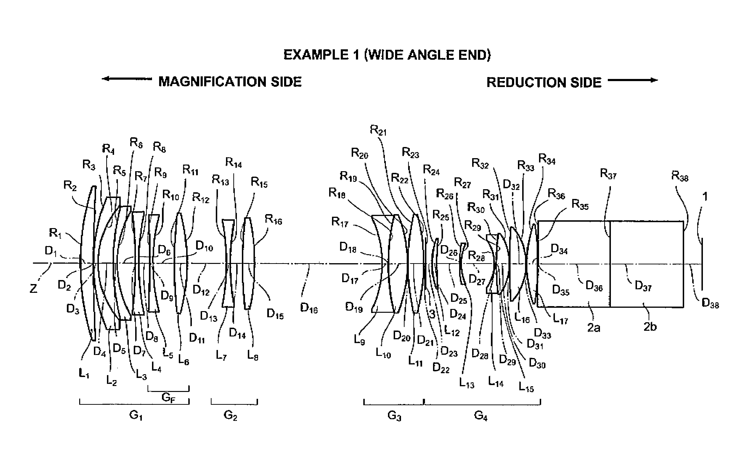
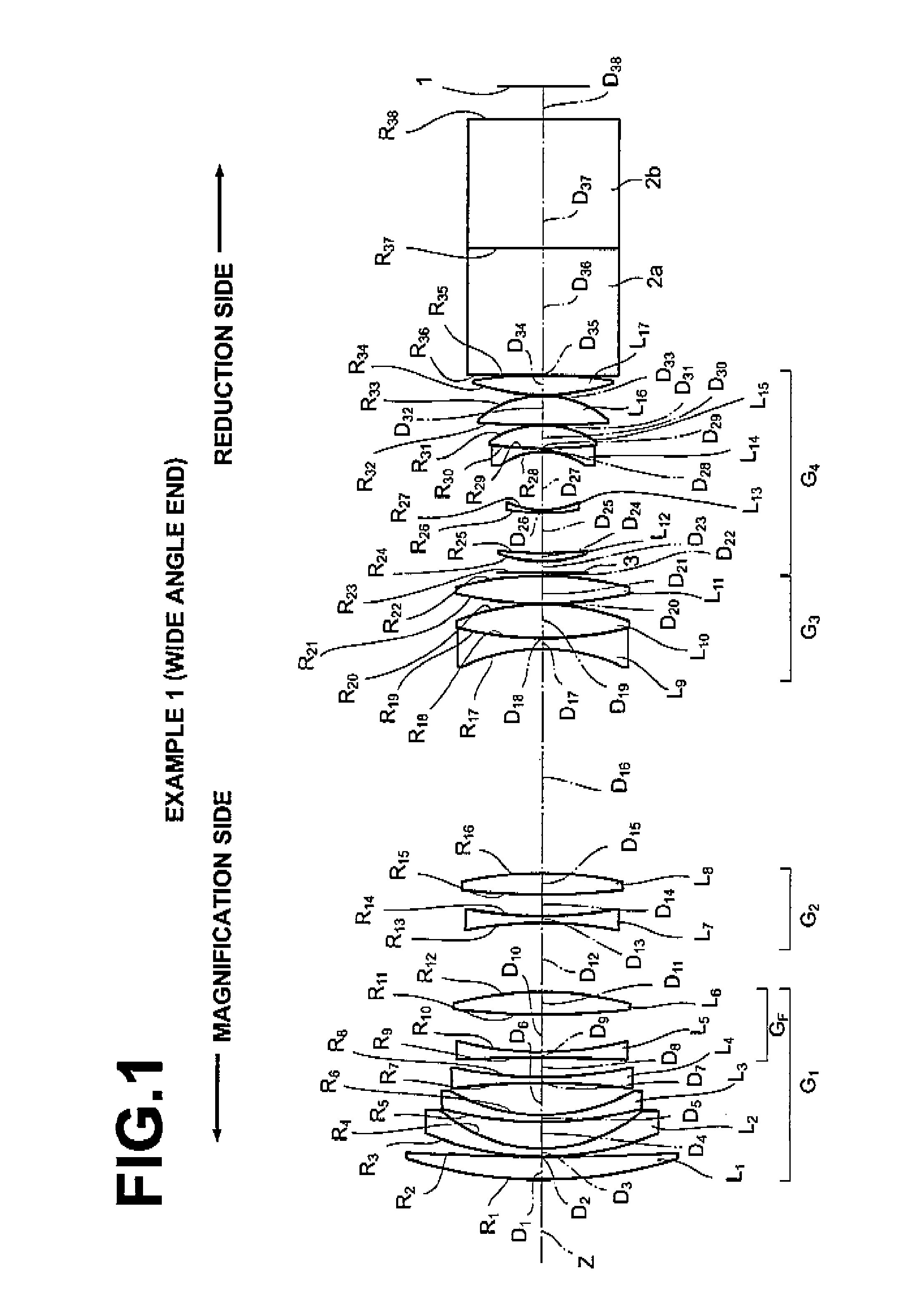
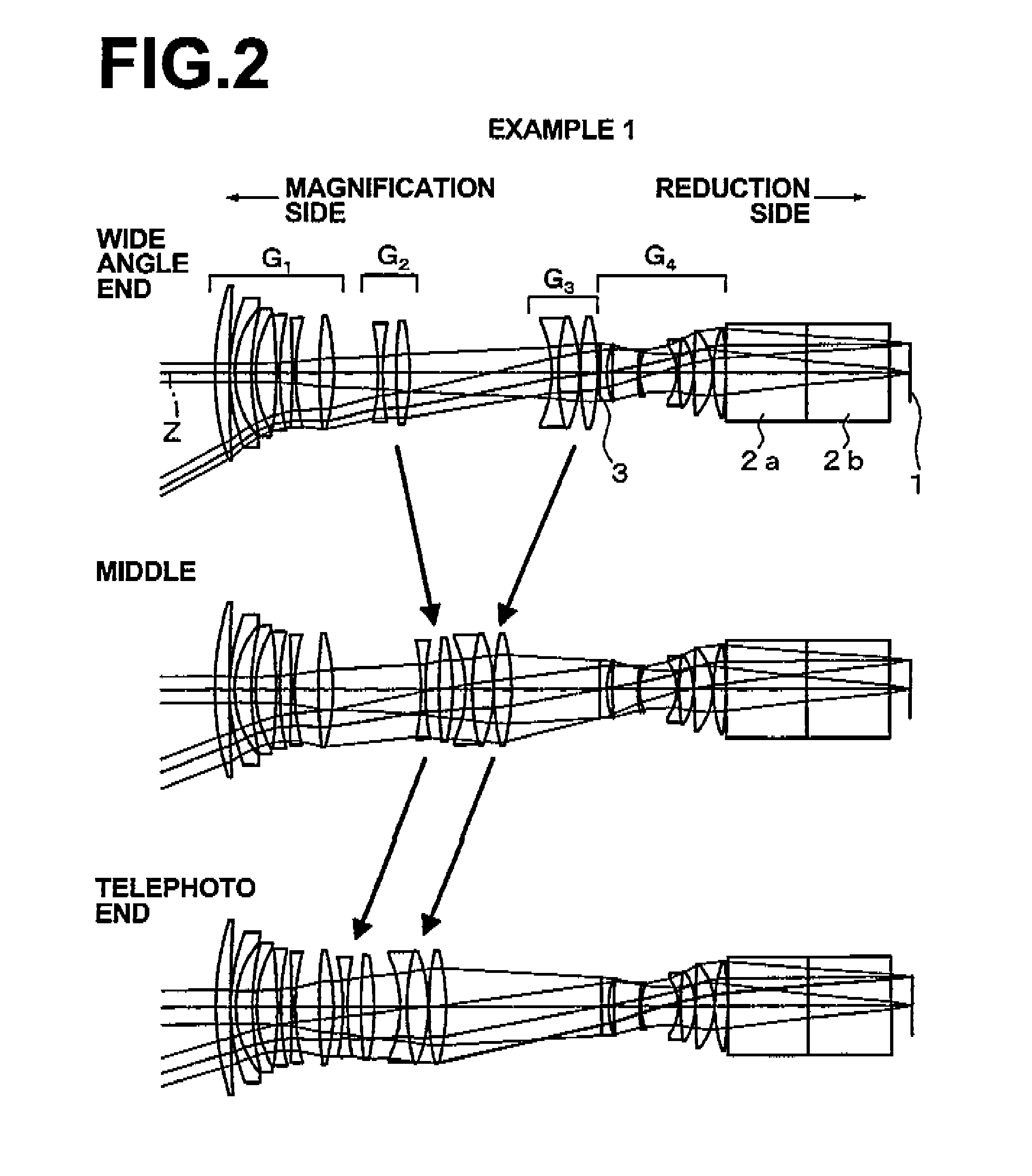
[0341]First, with reference to FIGS. 1 and 2, a first embodiment of the present invention will be described. A variable magnification optical system according to the first embodiment of the present invention is a zoom lens for projection. FIG. 1 is a diagram illustrating the structure of the zoom lens for projection in the first embodiment of the present invention. FIG. 1 corresponds to Example 1, which will be described later. FIG. 2 is a diagram illustrating a position to which each lens group moves at wide angle end, at middle position and at telephoto end when variable magnification operations are performed on the zoom lens illustrated in FIG. 1. Arrows in FIG. 2 schematically illustrate the directions of movement of movable lens groups (moving lens groups) when the zoom lens moves from wide angle end to middle position, and from middle position to telephoto end. Further, FIG. 2 illustrates paths of rays entering the zoom lens, i.e., axial rays and off-axial rays at a m...

second embodiment

Variable Magnification Optical System

[0374]Next, with reference to FIGS. 13 and 14, a second embodiment of the present invention will be described. The second embodiment of the present invention is a variable magnification optical system for projection. The variable magnification optical system for projection according to the second embodiment may be embodied in the following first through third modes. The example illustrated in FIGS. 13 and 14 includes the first through third modes. The second embodiment will be described by using the optical system illustrated in FIGS. 13 and 14 as an example.

[0375]FIG. 13 is a diagram illustrating the lens structure of the variable magnification optical system for projection in the second embodiment of the present invention. FIG. 13 corresponds to Example 7, which will be described later. FIG. 14 is a diagram illustrating a position to which each lens group moves at wide angle end, at middle position and at telephoto end when variable magnificati...

example 1

[0487]FIG. 1 is a diagram illustrating the structure of a zoom lens for projection in Example 1. FIG. 2 is a diagram illustrating movement paths of lens groups. FIG. 2 illustrates positions of the lens groups at wide angle end (projection distance is 7583.0 mm), at middle position (projection distance is 7583.0 mm), and at telephoto end (projection distance is 7583.0 mm) (same for FIGS. 4, 6, 8, 10 and 12, which will be described later). As illustrated in FIGS. 1 and 2, the zoom lens for projection in Example 1 is composed of first lens group G1 having negative refractive power, second lens group G2 having negative refractive power, third lens group G3 having positive refractive power, and fourth lens group G4 having positive refractive power, which are arranged from the magnification side of the zoom lens in the order mentioned above. Further, the reduction side of the zoom lens for projection is telecentric. Further, an image display plane 1 of a light valve, such as a reflective ...


PUM


Abstract

A variable magnification optical system for projection includes a first-lens-group having negative refractive power, and which is fixed when magnification of the system is changed, a second-lens-group having negative refractive power, and which is movable when magnification of the system is changed, a third-lens-group having positive refractive power, and which is movable when magnification of the system is changed, and a fourth-lens-group having positive refractive power, and which is fixed when magnification of the system is changed, which are arranged from the magnification side of the system in the order mentioned. The reduction side of the variable magnification optical system is telecentric, and formula 1.5<Bf / fw is satisfied, where Bf: back focus in air of entire system at wide angle end, and fw: focal length of entire system at wide angle end.

Description

BACKGROUND OF THE INVENTION[0001]1. Field of the Invention[0002]The present invention relates to a variable magnification optical system for projection and a zoom lens for projection that are mountable on projection-type display apparatuses or the like, and the projection-type display apparatuses. Particularly, the present invention relates to a variable magnification optical system for projection and a zoom lens for projection, and projection-type display apparatuses suitable to project images onto large screens at movie theaters or the like.[0003]2. Description of the Related Art[0004]Conventionally, projector apparatuses (projection-type display apparatuses) using light valves, such as a liquid crystal display device and a DMD display device, and which have relatively long back focus, were widely used.[0005]In recent years, movie theaters or the like started using projector apparatuses that can project precise images appropriate for large screens.[0006]Such projector apparatuses ...

Claims


Application Information

Patent Timeline
Patent Type & Authority Patents(United States)
IPC IPC(8): G02B15/14G02B13/22
CPCG02B15/177G02B15/144513G02B15/145529
Inventor NAGATOSHI, YUKIKONAGAHARA, AKIKO
Owner FUJIFILM CORP
Why Eureka
Try Eureka