Measuring instrument housing with a display panel

a technology of display panel and measuring instrument, which is applied in the field of measuring instrument housing, can solve the problems of negative influence on and achieve the effect of improving the sealing quality of resin

Inactive Publication Date: 2014-04-15
KROHNE MESSTECHNICK GMBH & CO KG
View PDF16 Cites 0 Cited by
  • Summary
  • Abstract
  • Description
  • Claims
  • Application Information

AI Technical Summary

Benefits of technology

[0008]The primary object of the present invention is thus to provide a measuring instrument housing with improved resin sealing.
[0012]The inserted display panel can, in this way, be arranged in the display panel holding fixture in such a manner that the display panel is sealed against the viewing window, but not in direct contact with the display panel holding fixture, rather only has indirect contact with the display panel holding fixture via the seal and the surrounding resin. In this manner, mechanical forces due, for example, to different temperature coefficients of the display panel and the measuring instrument can be accommodated by the hardened resin. Naturally, the resin is selected to have a sufficient elasticity even in the hardened state for this purpose. The mechanical forces, consequently, cannot damage either the housing or the display panel.
[0013]The liquid resin is filled into the resin receptacle before inserting the display panel into the display panel holding fixture. In order to measure the amount of resin filled, one or more observable markings can be provided on the seal and / or on the display panel holding fixture. The difference volume of the resin that has overflowed into the resin slot from the resin receptacle due to insertion of the display panel is exactly measured with the help of the markings so that the resin slot is filled. Thus, contamination of the inside of the measuring instrument housing or the display panel due to amounts of resin that are too large are eliminated. The risk of having an amount of resin that is not enough is also eliminated.
[0015]In a further preferred design of the invention, the seal has a seal base and a deformable structure, wherein the seal base is adapted in shape to the seal holding fixture and the deformable structure is deformed when the display panel has been inserted. Preferably, the seal holding fixture holds the seal base in a twist-proof manner, meaning that twisting of the seal inserted in the seal holding fixture upon insertion of the display panel is prevented by the spatial design and adaptation of the seal base on the seal holding fixture. Preferably, materials for the seal include elastomers and / or compressible foams. The use of these materials allows for a low-cost and simple production of the seals.

Problems solved by technology

In measuring instrument housings from the prior art, when the resin is introduced it flows from top to bottom in the resin slot, due to gravity, which can lead to the entrapment of air bubbles, which can negatively influence the sealing quality of the resin.

Method used


Image

  • Measuring instrument housing with a display panel
  • Measuring instrument housing with a display panel
  • Measuring instrument housing with a display panel

Examples


third embodiment

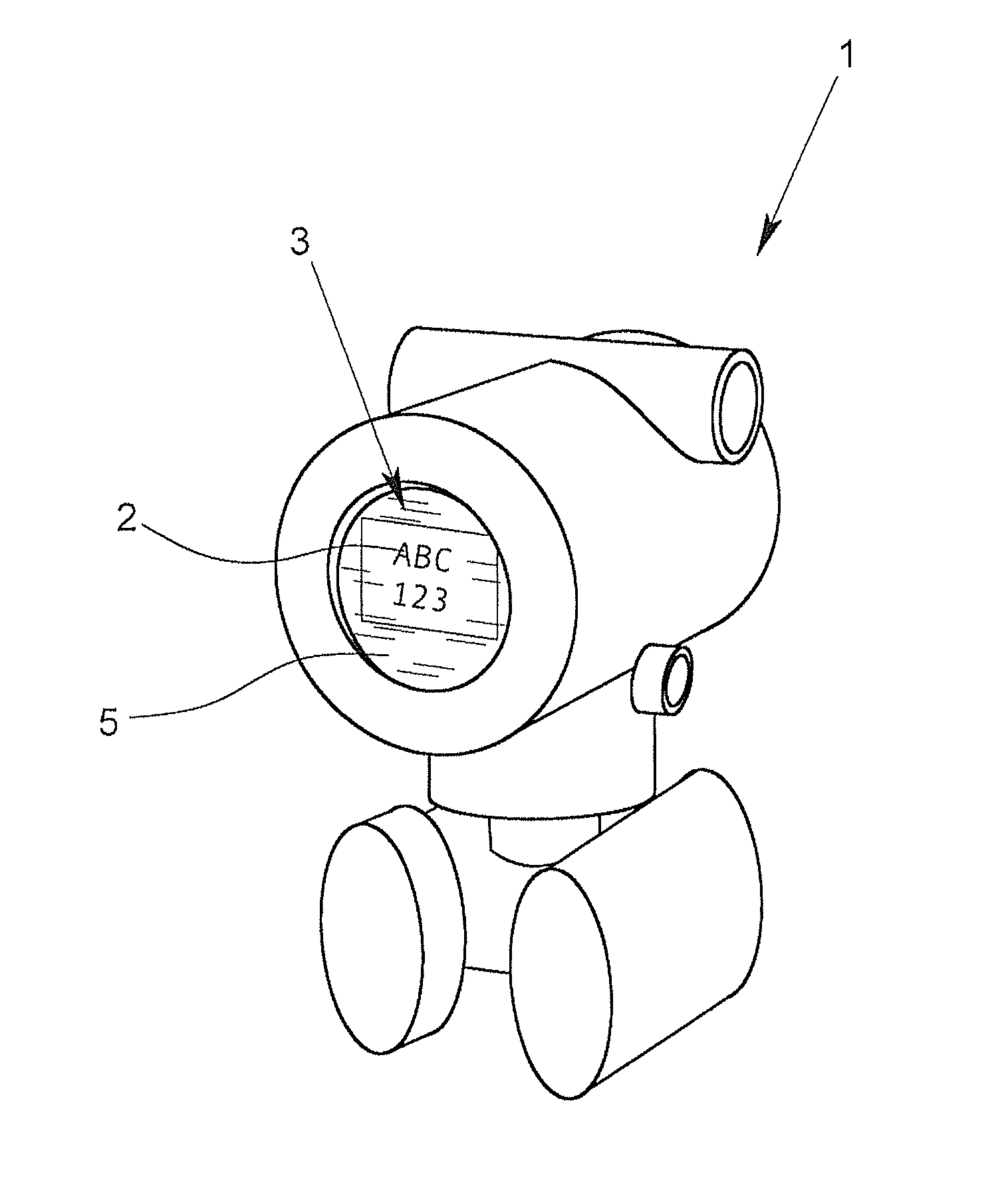
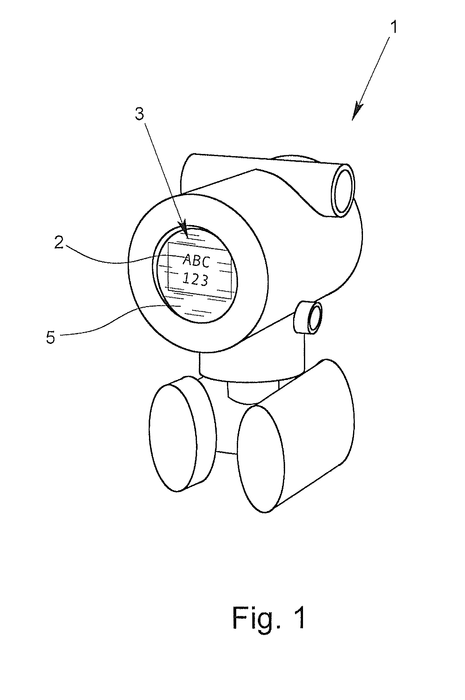
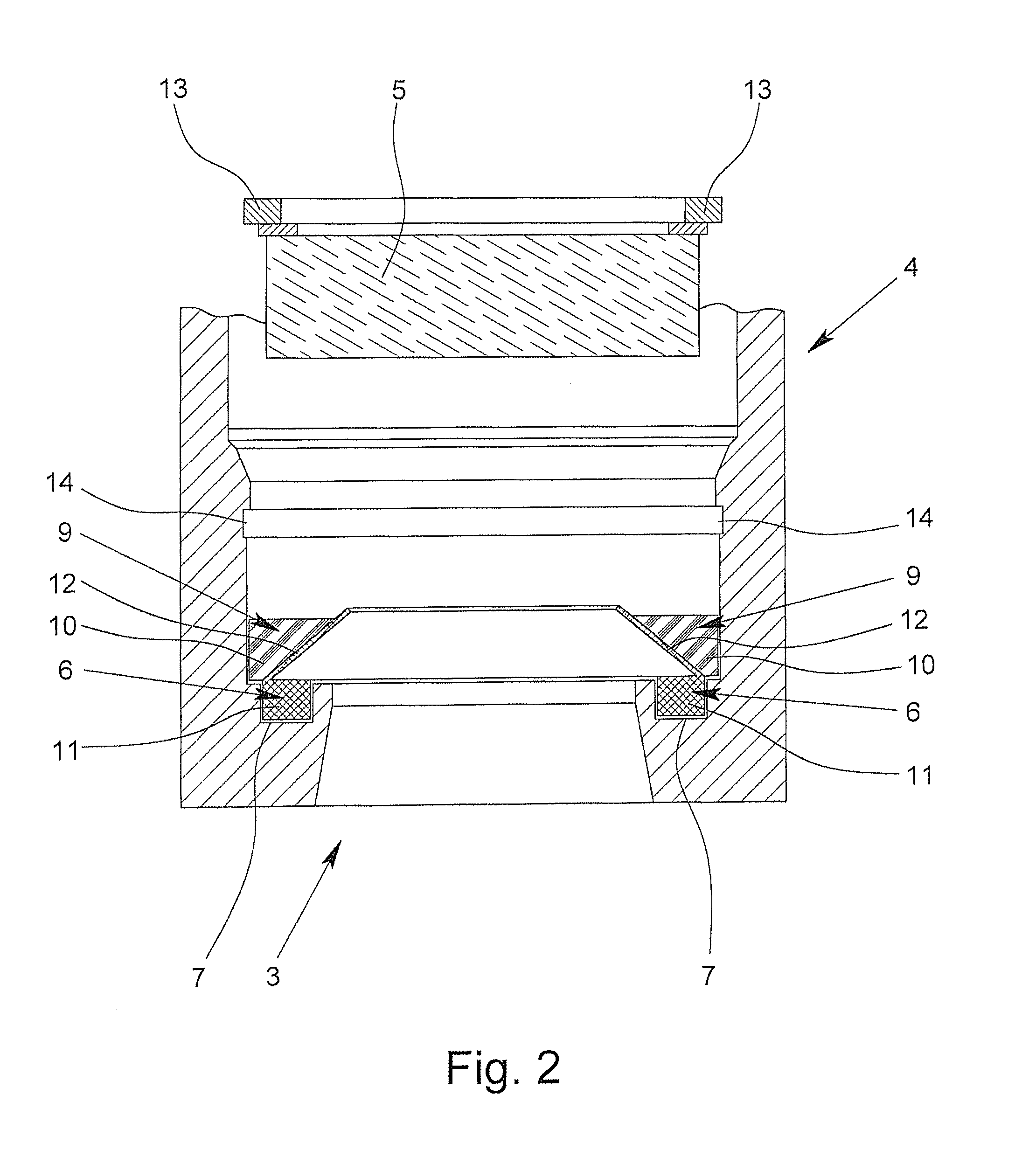
[0034]FIG. 6 shows a section in a sectional side view of the measuring instrument housing 1 according to the invention with a display panel 5 inserted in the display panel holding fixture 4 on the left side and with a display panel 5 that is not inserted on the right side. The seal holding fixture 7 is a groove running around the viewing window 3 having a rectangular cross section. The seal base 11 of the seal 6 is adapted in shape to the seal holding fixture 7. The seal 6 ends flush with the viewing window 3. If the display panel 5 has not been inserted, the deformable structure 12 of the seal 6 is initially bent within the display panel holding fixture 4. If the display panel 5 has been inserted, the deformable structure 12 lies flat on the display panel holding fixture 4. In this manner, a particularly large sealing area results between display panel holding fixture 4 and display panel 5 due to the seal 6. The display panel 5 is mechanically fixed by an outer threaded ring 16, wh...

fourth embodiment

[0035]FIG. 7 shows a section in a sectional side view of the measuring instrument housing 1 according to the invention. On the left side, the display panel 5 has been inserted and on the right side, the display panel 5 has not been inserted. The seal holding fixture 7 is a groove with a rectangular cross-section, milled around the viewing window 3. The seal 6 is a ring-shaped seal with a circular cross-section. The volume and the elasticity of the seal 6 are measured in such a manner that display panel 5 inserted in the display panel holding fixture 4 pushes the seal 6 in the seal holding fixture 7 so that the display panel 5 lies against the display panel holding fixture 4 and the seal 6 fills the seal holding fixture 7.


PUM

PropertyMeasurementUnit
widthaaaaaaaaaa
widthaaaaaaaaaa
viscosityaaaaaaaaaa

Abstract

An intrinsically safe housing for a measuring instrument, having a viewing window for the display panel of a measuring instrument, an instrument display panel holding fixture for receiving an instrument display panel provided around the viewing window, said holding fixture having an inner void having a volume greater than a volume of the instrument display panel, a difference between said volumes forming a resin slot surrounding the instrument display panel upon its insertion, and a seal holding fixture provided around the viewing window containing a seal for sealing a front surface of said display panel, wherein the seal and the display panel holding fixture form a resin receptacle for a flowable resin, and the resin slot receives an overflow of said resin upon insertion of said instrument display panel.

Description

BACKGROUND OF THE INVENTION[0001]1. Field of the Invention[0002]The invention relates to a measuring instrument housing having a viewing window, a display panel holding fixture being provided around the viewing window, a display panel on a measuring instrument that can be inserted in the display panel holding fixture, a seal for creating a seal with resin between the display panel when inserted in the display panel holding fixture and the display panel holding fixture, a seal holding fixture provided around the viewing window in the display panel holding fixture for holding the seal, and a circumferential resin slot provided between the display panel and the display panel holding fixture.[0003]2. Description of Related Art[0004]Measuring instrument housings serve to accommodate measuring instruments that measure, e.g., a process variable such as the flow of a medium through a tube. A measuring instrument generally includes mechanical, electrical and electronic components and often a...

Claims


Application Information

Patent Timeline
Patent Type & Authority Patents(United States)
IPC IPC(8): G01D11/24G01P1/02G01L19/14
CPCG01D11/26
Inventor WERNER, THOMASLUEBBERS, WILHELM
Owner KROHNE MESSTECHNICK GMBH & CO KG
Why Eureka
Try Eureka