Zoom lens

a zoom lens and zoom technology, applied in the field of zoom lenses, can solve the problems of large outer diameter, difficult control of large outer diameter of the lens group, etc., and achieve the effect of reducing the zoom lens, preventing aberrations over the entire zoom range, and reducing the size of the zoom lens

Inactive Publication Date: 2014-04-15
FUJIFILM CORP
View PDF10 Cites 2 Cited by
  • Summary
  • Abstract
  • Description
  • Claims
  • Application Information

AI Technical Summary

Benefits of technology

[0008]The present invention has been developed in view of the circumstances described above, and it is an object of the present invention to provide a three-group zoom lens which is compact, yet capable of preventing aberrations over the entire zoom range.
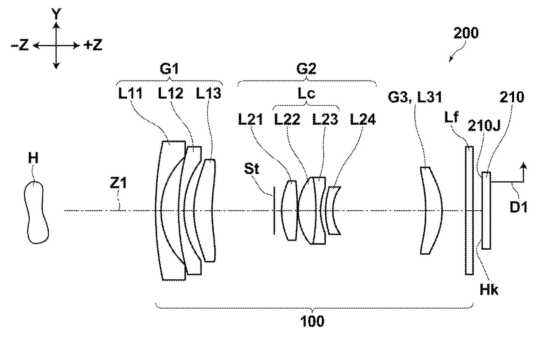
[0027]According to the zoom lens of the present invention, a first lens group having a negative power, a second lens group having a positive power, and a third lens group having a positive power are arranged in this order from an object side and an aperture stop which is moved integrally with the second lens group is provided, and zooming is performed by changing a distance between the first and second lens groups and a distance between the second and third lens groups. Here, the first lens group is composed of a first group first lens having a negative power with a concave surface facing an image side, a first group second lens having a negative power with a concave surface facing the image side, and a first group third lens having a positive power and at least one aspheric surface with a convex surface facing the object side arranged in this order from the object side, the second lens group is composed of a second group first lens having a positive power with a convex surface facing the object side, a cemented lens having a positive power as a whole, and a second group fourth lens having a negative power and at least one aspheric surface with a concave surface facing the image side arranged in this order from the object side, in which the cemented lens is composed of a second group second lens having a positive power with a convex surface facing the object side and a second group third lens having a negative power with a concave surface facing the image side arranged in this order from the object side, and the third lens group is composed of a third group first lens having a positive power. This allows downsizing of the zoom lens while preventing aberrations over the entire zoom range.
[0028]That is, as the lens on the most image side in the second group is a negative lens, the positive lenses on the object side in the second lens group may be formed to have a strong refractive power. This allows effective diameters of the lenses in the second lens group to be reduced so that the outer diameter of the entire second lens group may be reduced. Further, as the lens on the most image side in the second lens group has at least one aspheric surface, aberrations may be prevented more reliably over the entire zoom range.
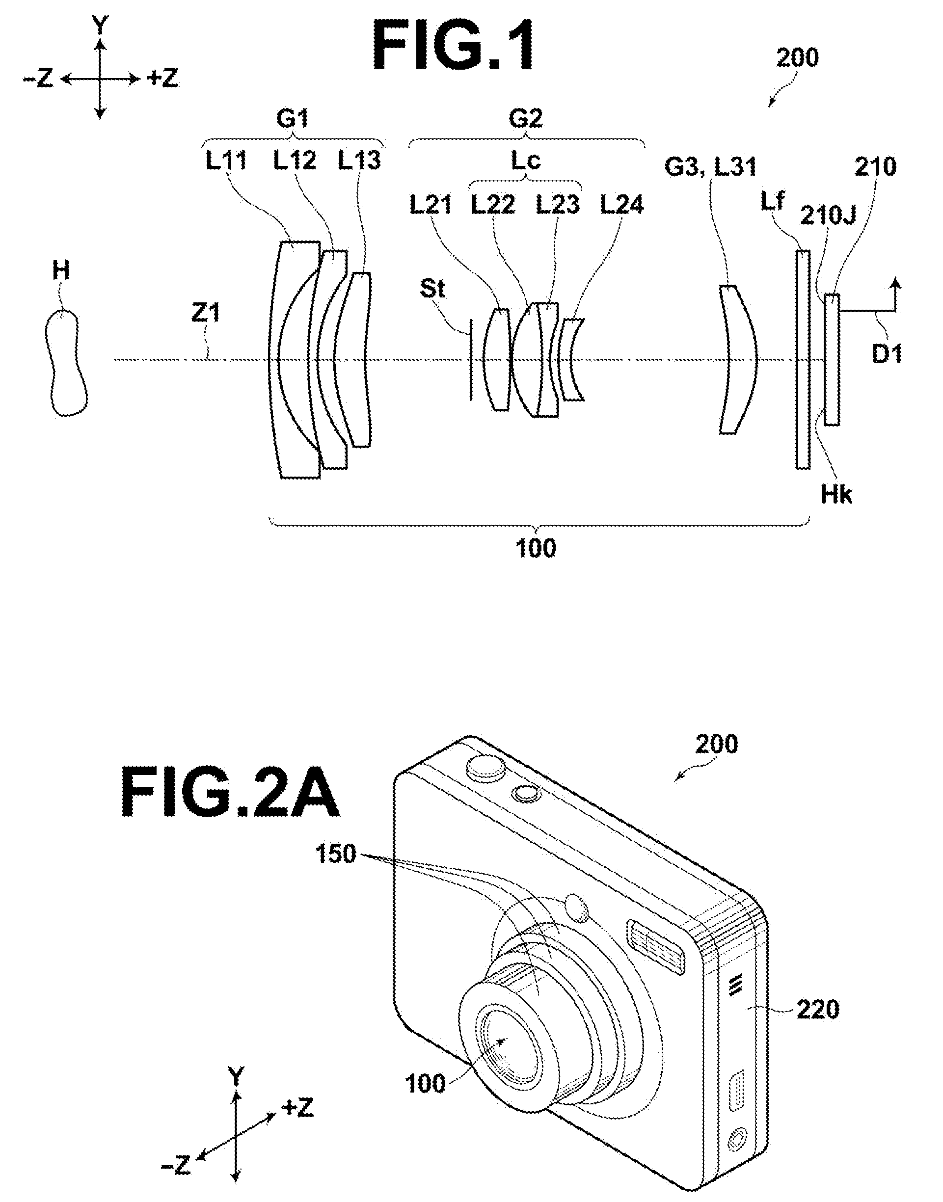
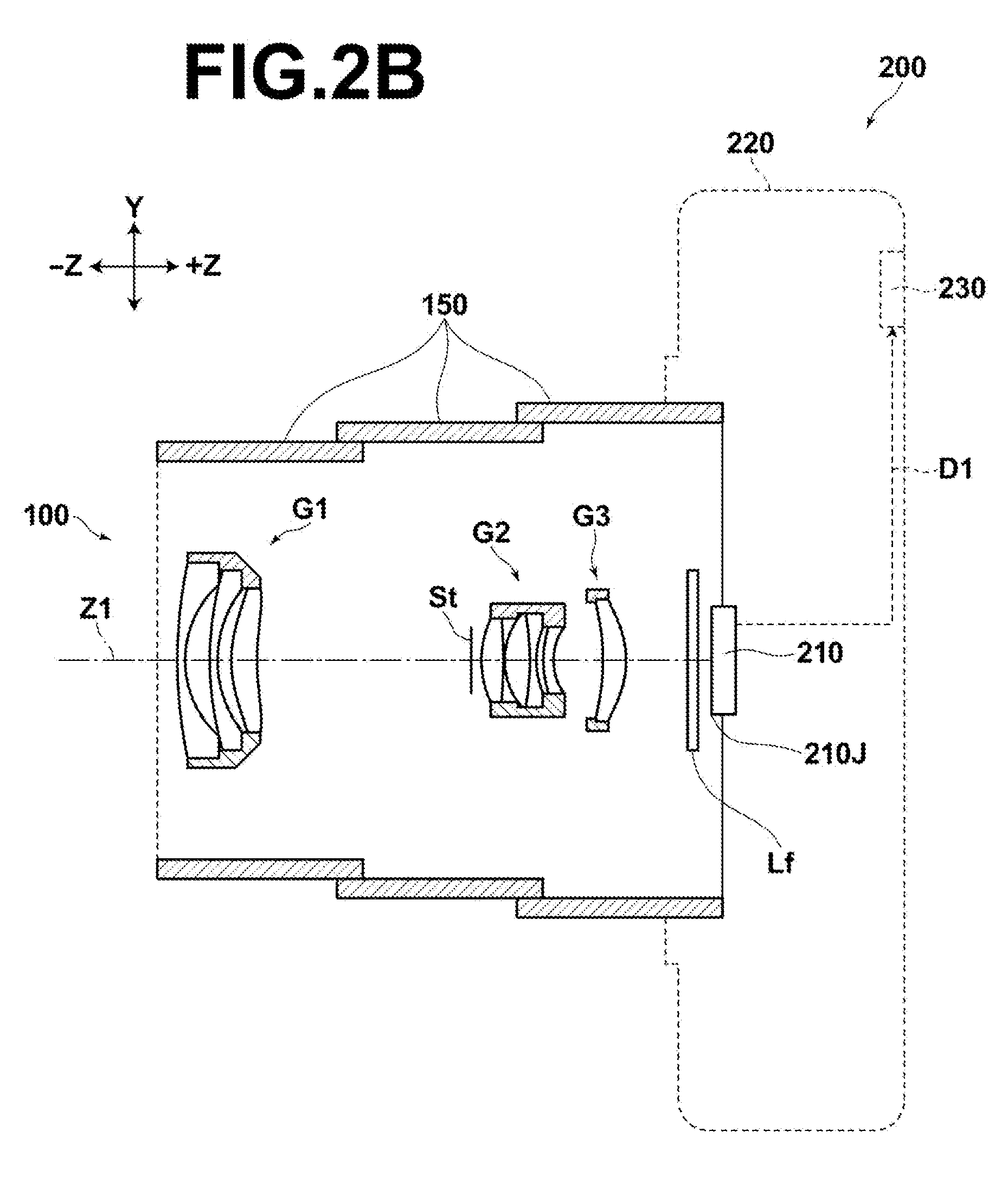
[0029]Further, if the zoom lens of the present invention is constructed so as to be retracted inside of an image pickup apparatus by moving the second lens group of the zoom lens in a direction orthogonal to the optical axis and moving the entire zoom lens in an optical direction, the thickness of the zoom lens, when retracted, in the optical axis direction may be reduced.
[0030]That is, for example, more and more recent digital cameras employ a retraction method, when retracting a zoom lens inside of an image pickup apparatus, in which the entire zoom lens is retracted inside of the image pickup apparatus by shifting a particular lens group in a direction perpendicular to the optical axis and moving each lens group in the optical axis direction. In that case, each lens group is moved in the optical axis direction and retracted such that the lens group shifted in a direction orthogonal to the optical axis and other lens groups are not overlapped in the optical axis direction. Here, it is demanded that the thickness of the entire zoom lens in the optical axis direction, when it is retracted, be reduced and the outer diameter of the lens barrel, when the entire zoom lens is retracted inside of the image pickup apparatus, be reduced by reducing the outer diameter of the lens group to be shifted in a direction orthogonal to the optical axis.
[0031]According to the structure of the zoom lens of the present invention described above, the use of a negative lens as the lens disposed on the most image side in the second lens group allows the outer diameter of the second lens group which is smaller than the other lens groups (first and third lens groups) due to being positioned near the aperture stop to be further reduced. Thus, if an arrangement is adopted in which the entire zoom lens is retracted by moving the second lens group in a direction orthogonal to the optical axis and moving the entire zoom lens in the optical axis direction, the thickness of the entire zoom lens in the optical axis direction and the outer diameter thereof, when it is retracted, may be reduced, as described above. Therefore, the space required to retract the entire zoom lens inside of the image pickup apparatus may be reduced.

Problems solved by technology

This zoom lens has a problem that the second lens group has a large outer diameter because the positive lenses on the object side in the second zoom lens are formed to have a weak power since the lens on the most image side in the second lens group is a positive lens and effective diameters of the positive lenses on the object side need to be increased.
The zoom lens in which the lens on the most image side is a negative lens in the second lens group as described above has a problem that it is difficult to control aberrations over the entire zoom range when the zoom ratio is increased to 5× because the power of the first lens group is increased.
This zoom lens has a problem that the second lens group has a large outer diameter because the positive lenses on the object side in the second zoom lens are formed to have a weak power since the lens on the most image side in the second lens group is a positive lens and effective diameters of the positive lenses on the object side need to be increased, as in the zoom lens described in U.S. Pat. No. 6,452,729.

Method used


Image

  • Zoom lens
  • Zoom lens
  • Zoom lens

Examples


specific examples

[0103]Hereinafter, numerical data and the like of Examples 1 to 7 of the zoom lens according to the present invention will be described with reference to FIGS. 3 to 17 and Tables 1 to 8.

[0104]FIG. 3 is a cross-sectional view, commonly illustrating a schematic configuration of zoom lenses of Examples 1 to 7 when the zoom is set to a wide angle end.

[0105]FIGS. 4 to 10 are cross-sectional views of the zoom lenses of Examples 1 to 7 respectively, each illustrating schematic configurations thereof when the zoom is set to a wide angle end, a telephoto end, and a midpoint thereof and comparatively illustrating the states in which the zoom is set to the wide angle end, midpoint, and telephoto end in this order.

[0106]FIGS. 11 to 17 show various aberrations of zoom lenses of Example 1 to 7 respectively. Each drawing illustrates aberrations of each zoom lens when the zoom is set to the wide angle end, midpoint, and telephoto end in this order.

[0107]Note that the same symbols in FIGS. 3 to 10 a...


PUM


Abstract

A zoom lens includes a first lens group having a negative power, a second lens group having a positive power, and a third lens group having a positive power arranged in this order from an object side and an aperture stop which is moved integrally with the second lens group, and performs zooming by changing a distance between the first and second lens groups and a distance between the second and third lens groups, wherein the second lens group is composed of a second group first lens having a positive power with a convex surface facing the object side, a cemented lens having a positive power as a whole, and a second group fourth lens having a negative power and at least one aspheric surface with a concave surface facing the image side arranged in this order from the object side.

Description

TECHNICAL FIELD[0001]The present invention relates to a zoom lens and more specifically to a three-group zoom lens.BACKGROUND ART[0002]Heretofore, in image pickup optical systems of digital cameras and the like required to be compact and have a high zoom ratio, a four-group zoom lens having a relatively high zoom ratio of about 5× has been known.[0003]Further, despite having a zoom ratio of about 3×, a three-group zoom lens with an intention to further reduce the size by reducing the number of lenses has also been known as described, for example, in U.S. Pat. Nos. 6,452,729, 6,618,210, and Japanese Unexamined Patent Publication No. 2003-307677.DISCLOSURE OF THE INVENTION[0004]The zoom lens described in U.S. Pat. No. 6,452,729 includes a first lens group having a negative power (hereinafter, also referred to as the “negative first lens group” for short), a positive second lens group, and a positive third lens group. The first lens group includes a lens having a negative power (herein...

Claims


Application Information

Patent Timeline
Patent Type & Authority Patents(United States)
IPC IPC(8): G02B15/177
CPCG02B15/14G02B15/177G02B15/143507
Inventor ORI, TETSUYA
Owner FUJIFILM CORP
Why Eureka
Try Eureka