Mobile communication method and radio base station

a mobile communication and radio base station technology, applied in the field of mobile communication methods and radio base stations, can solve the problems of mobile communication systems employing lte systems, the service gateway apparatus s-gw cannot know how long the serving gateway apparatus s-gw can wait,

Inactive Publication Date: 2014-04-15
NTT DOCOMO INC
View PDF5 Cites 224 Cited by
  • Summary
  • Abstract
  • Description
  • Claims
  • Application Information

AI Technical Summary

Benefits of technology

[0009]The present invention has been made in view of the aforementioned problems. An objective of the invention is thus to provide a mobile communication method and a radio base station which allow the serving gateway apparatus S-GW to detect completion of the transfer of the consecutive uplink data to the serving gateway apparatus S-GW (or handover destination radio base station T-eNB) by the handover source radio base station S-eNB, when a mobile station UE performs an X2 handover and an S1 handover.
[0010]In addition, the present invention has been made in view of the aforementioned problems. Another objective of the invention is thus to provide a mobile communication method and a radio base station which allows the handover destination radio base station T-eNB to detect completion of the transfer of the downlink data to the handover destination radio base station T-eNB by the handover source radio base station S-eNB, when a mobile station UE performs an S1 handover.

Problems solved by technology

However, in the conventional mobile communication system employing the LTE system, there is a problem that, when a mobile station UE performs an X2 handover and an S1 handover, the serving gateway apparatus S-GW cannot know how long the serving gateway apparatus S-GW needs to hold the U-plane resource (GTP-U tunnel), because the serving gateway apparatus S-GW (or handover destination radio base station T-eNB) cannot detect completion of the transfer of the consecutive uplink data to the serving gateway apparatus S-GW by the handover source radio base station S-eNB.
In addition, there is another problem in the conventional mobile communication system employing the LTE system.
The problem is that, when a mobile station UE performs an S1 handover, the handover destination radio base station T-eNB cannot perform sequence control between the downlink data received from the serving gateway apparatus S-GW and the downlink data received from the handover source radio base station S-eNB, because the handover destination radio base station T-eNB cannot detect completion of the transfer of the downlink data to the handover destination radio base station T-eNB by the handover source radio base station S-eNB.

Method used


Image

  • Mobile communication method and radio base station
  • Mobile communication method and radio base station
  • Mobile communication method and radio base station

Examples


first embodiment

(Mobile Communication System Of Present Invention)

[0036]A mobile communication system according to a first embodiment of the present invention will be described with reference to FIGS. 1 and 2.

[0037]In this embodiment, a mobile communication system employing the LTE (Long Term Evolution) system is used as an example to describe the embodiment. However, the present invention is applicable to a system other than the aforementioned mobile communication system.

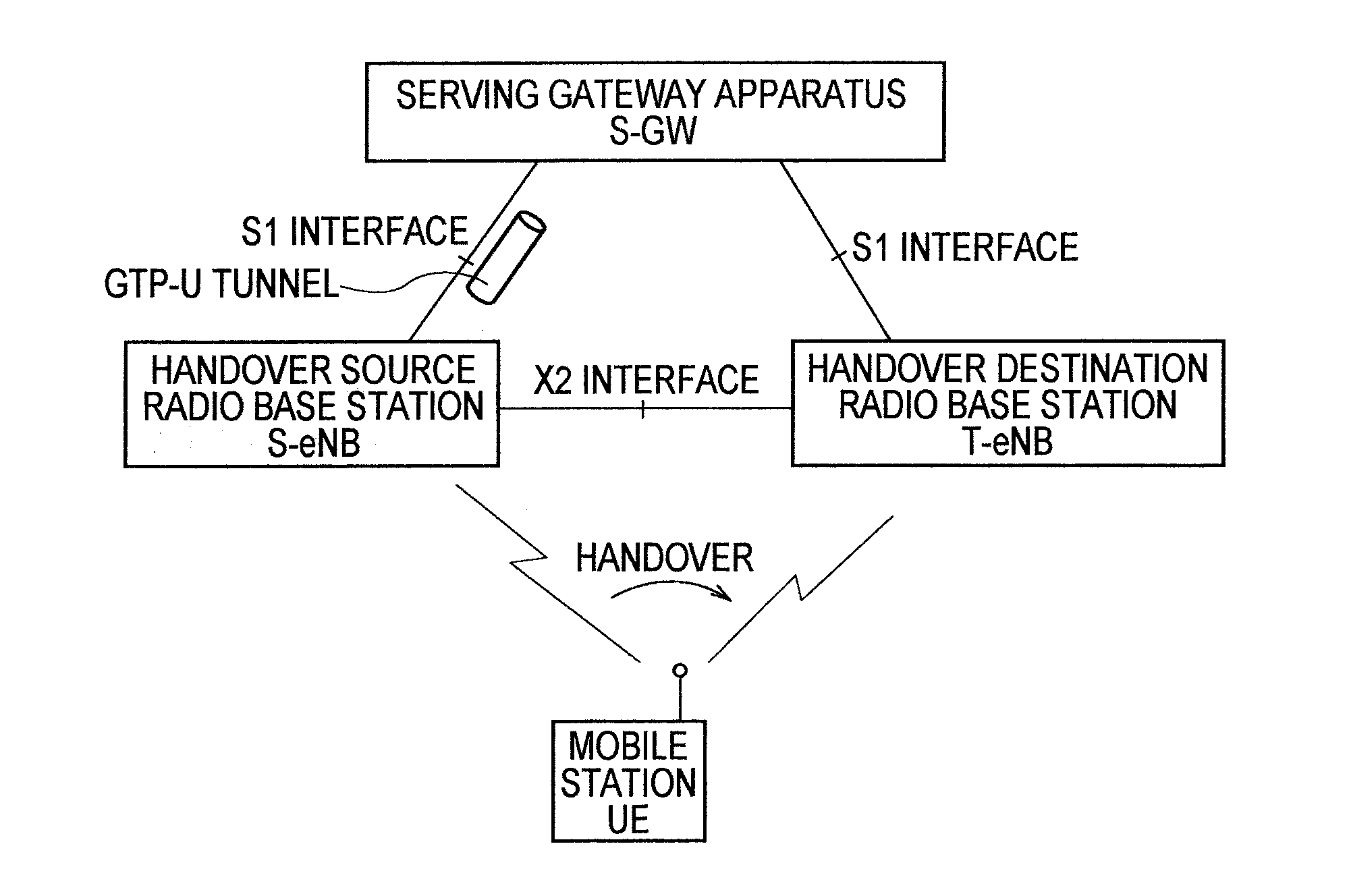
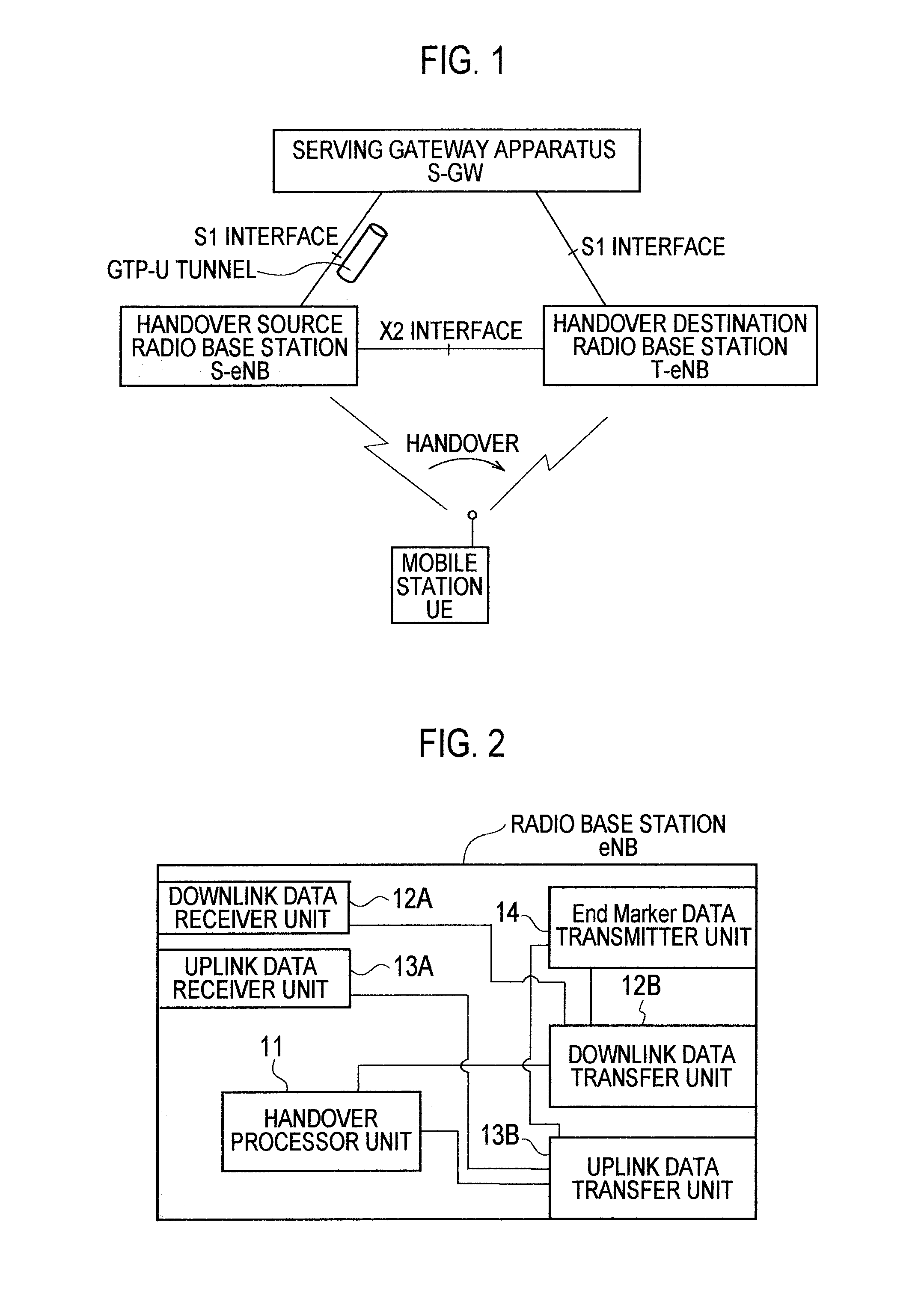
[0038]As shown in FIG. 1, in this embodiment, a description will be given of an example of a case where a mobile station UE performs a handover (X2 handover, Inter-eNB handover) from a cell (handover source cell) controlled by a handover source radio base station (first radio base station) S-eNB to a cell (handover destination cell) controlled by a handover destination radio base station (second radio base station) T-eNB.

[0039]As shown in FIG. 2, a radio base station eNB according to the first embodiment includes a handover proce...

second embodiment

(Mobile Communication System of Present Invention)

[0068]A description will be given of a mobile communication system according to a second embodiment of the present invention with reference to FIGS. 5 through 7. In the following description of the mobile communication system according to the second embodiment, the mobile communication system will be described focusing on differences from the mobile communication system according to the first embodiment described above.

[0069]As shown in FIG. 5, in this embodiment, a description will be given of an example focusing on downlink data of a case where a mobile station UE performs a handover (S1 handover, Inter-eNB handover) from a cell (handover source cell) controlled by a handover source radio base station (first radio base station) S-eNB to a cell (handover destination cell) controlled by a handover destination radio base station (second radio base station) T-eNB.

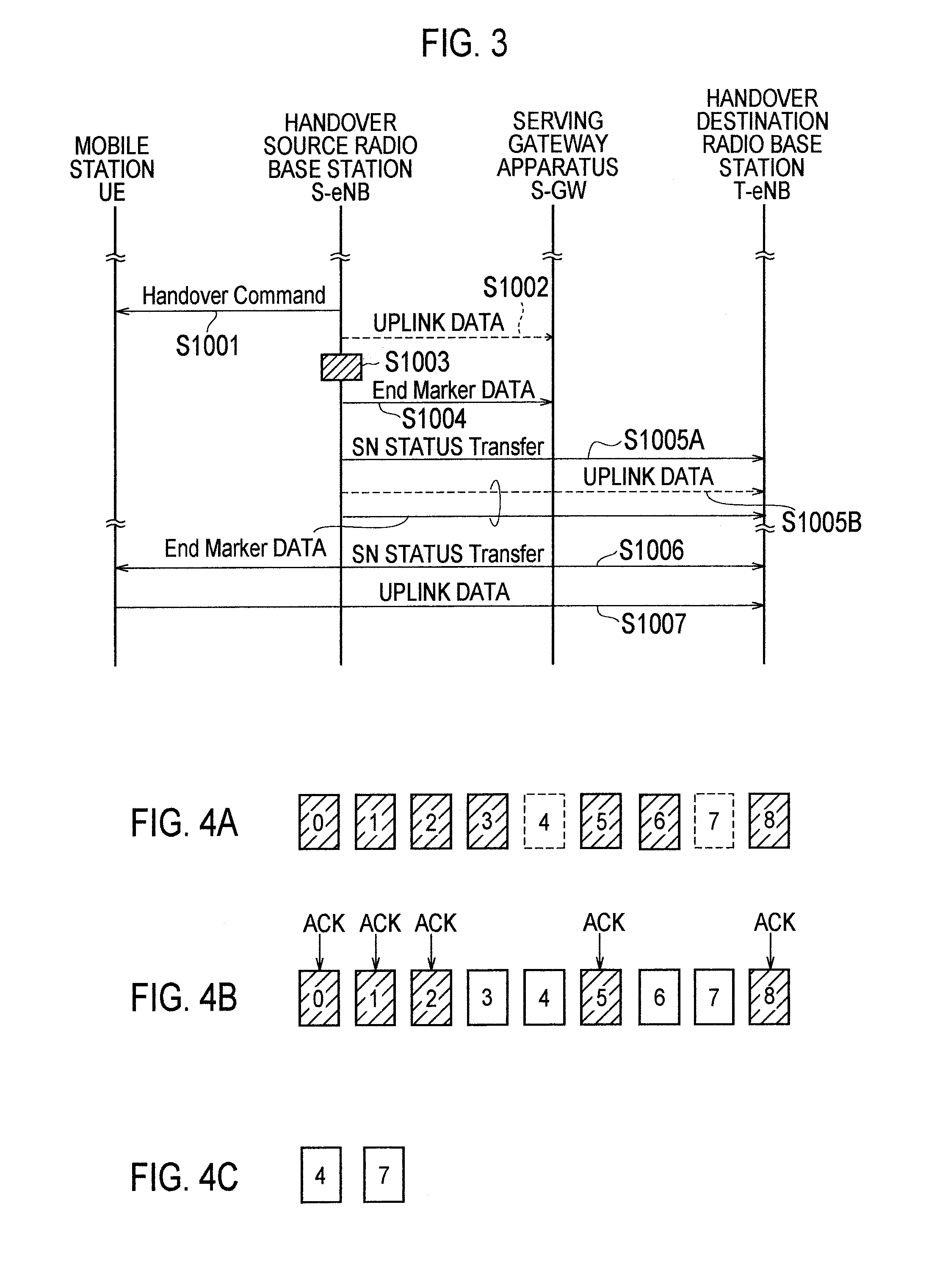
[0070]In this embodiment, the End Marker data transmitter unit 14 of the...

third embodiment

Mobile Communication System of Present Invention)

[0086]A description will be given of a mobile communication system according to a third embodiment of the present invention with reference to FIGS. 5, 8 and 9. In the following description of the mobile communication system according to the third embodiment, the mobile communication system will be described focusing on differences from the mobile communication system according to the first embodiment described above.

[0087]As shown in FIG. 5, in this embodiment, a description will be given of an example focusing on uplink data in a case where a mobile station UE performs a handover (S1 handover, Inter-eNB handover) from a cell (handover source cell) controlled by a handover source radio base station (first radio base station) S-eNB to a cell (handover destination cell) controlled by a handover destination radio base station (second radio base station) T-eNB.

[0088]In this embodiment, the uplink data transfer unit 13B of the handover so...


PUM


Abstract

A mobile communication method according to the present invention includes: the steps of: (A) transferring, from a first radio base station (S-eNB) to an upper level node (S-GW), consecutive uplink data received from a mobile station (UE) with their sequence numbers being consecutive, by use of a resource allocated by the upper level node (S-GW), when the first radio base station (S-eNB) determines that the mobile station (UE) is to perform a handover; (B) transmitting, from the first radio base station (S-eNB) to the upper level node (S-GW) transfer completion notification data after the transfer of the consecutive uplink data to the upper level node (S-GW) is completed; and (C) releasing, at the upper level node (S-GW), the resource when receiving the transfer completion notification data.

Description

TECHNICAL FIELD[0001]The present invention relates to a mobile communication method and a radio base station.BACKGROUND ART[0002]In a mobile communication system employing the LTE (Long Term Evolution) system, which is specified in the 3GPP, a handover source radio base station S-eNB is configured to perform the following operation, when determining that a mobile station UE is to perform a handover (X2 handover) from a cell controlled by the handover source radio base station S-eNB to a cell controlled by a handover destination radio base station T-eNB. Here, the handover source radio base station S-eNB transfers consecutive uplink data (accumulated in a receiving buffer) to a serving gateway apparatus S-GW, by using a U-plane resource (GTP (GPRS Tunneling Protocol)-U tunnel) allocated between the handover source radio base station S-eNB and the serving gateway apparatus S-GW, and also transfers non-consecutive uplink data (accumulated in the receiving buffer) to the handover destin...

Claims


Application Information

Patent Timeline
Patent Type & Authority Patents(United States)
IPC IPC(8): H04W4/00
CPCH04W36/08H04W28/16H04W36/02H04W36/36
Inventor HAPSARI, WURI ANDARMAWANTIMOTEGI, MASAYUKIUCHIYAMA, TADASHI
Owner NTT DOCOMO INC
Why Eureka
Try Eureka