
Torque ripple suppression control apparatus and torque ripple suppression control method for rotating electrical machine

a technology of torque ripple and control apparatus, which is applied in the direction of motor/generator/converter stopper, dynamo-electric gear control, dynamo-electric converter control, etc., can solve the problem of difficulty in online compensation, and wariness or concern persists about adverse influence of analytical error. to achieve the effect of accurately suppressing torque rippl

Active Publication Date: 2014-04-22
MEIDENSHA ELECTRIC MFG CO LTD
View PDF6 Cites 14 Cited by
  • Summary
  • Abstract
  • Description
  • Claims
  • Application Information

AI Technical Summary

Benefits of technology

The present invention provides a technique for accurate suppression of torque ripple by identifying and cancelling out periodic disturbance in a system's transfer function. This technique can handle complicated electronic and mechanical characteristics such as multi inertia systems and inverter responses. The technique uses a periodic disturbance observer to determine the real and imaginary parts of the estimated current including the periodic disturbance, and then subtracts command compensating current from the system's transfer function to cancel out the periodic disturbance. This results in a more precise cancellation of torque ripple.

Problems solved by technology

A motor produces torque ripple (torque pulsation) in principle, and thereby causes various problems such as vibration, noise, adverse influence on ride quality and electrical and mechanical resonances.
However, wariness or concern persists about adverse influence of analytical error, for example, in a method of performing a feedforward compensation by using a mathematical analysis model.
Moreover, in a method of storing or memorizing a result of feedback learning control at a steady operating point, and performing feedforward compensation, online compensation is difficult because of time required for adjusting a control parameter adequately at each operation point.
Furthermore, in a method of reducing current ripple, optimum suppression is not guaranteed in terms of torque ripple.
However, the torque ripple observer compensation method is still insufficient in validation for characteristic in speed varying operation, and online feedback suppression.

Method used


Image

  • Torque ripple suppression control apparatus and torque ripple suppression control method for rotating electrical machine
  • Torque ripple suppression control apparatus and torque ripple suppression control method for rotating electrical machine
  • Torque ripple suppression control apparatus and torque ripple suppression control method for rotating electrical machine

Examples


Embodiment Construction

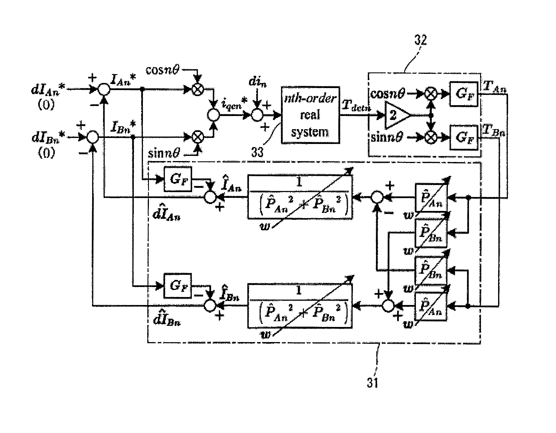
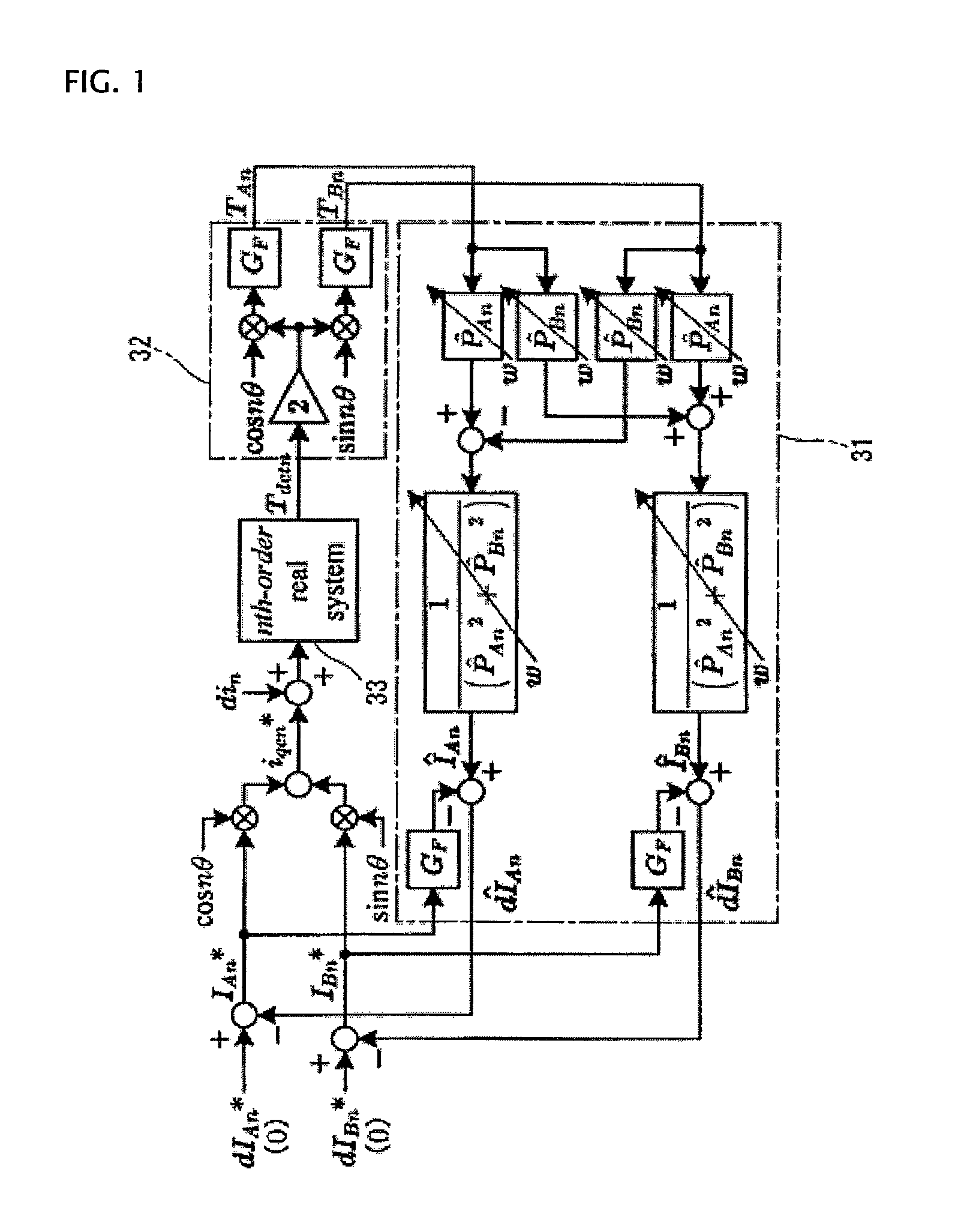
[0081]FIG. 1 is a calculation block diagram of a torque ripple suppression control with a periodic disturbance observer according to an embodiment of the present invention.

[0082]A torque ripple extracting section 32 (torque ripple pulsation frequency component extracting section 19 shown in FIG. 3) performs calculation based on the equations (3)˜(5), and determines an nth order torque pulsation extraction component (cosine coefficient) TAn and an nth order torque pulsation extraction component (sine coefficient) TBn. A periodic disturbance observer 31 (torque ripple suppression control section 21 shown in FIG. 3) is analogous to the periodic disturbance observer proposed by the non-patent document 1. However, in order to employ a structure with a torque ripple synchronizing coordinates, the periodic disturbance observer 31 uses an inverse characteristic of a one-dimensional complex vector expressed by equation (14), for a model of an inverse system for estimating a periodic disturba...


PUM


Abstract

A periodic disturbance observer determines real part I^An and imaginary part I^Bn of an estimated current including a periodic disturbance, from value of identification identifying a system transfer function of an nth order torque ripple frequency component from a command torque to a detected torque value, with a one-dimensional complex vector having a real part P^An and an imaginary part P^Bn, a cosine coefficient TAn, a sine coefficient TBn, and the real part P^An and imaginary part P^Bn of the system transfer function; subtracts command compensating current IAn* and IBn* obtained through pulsation extracting filter GF, respectively, from the real part I^An and imaginary part I^Bn of the estimated current, and thereby determines estimated periodic disturbance current real part dI^An and imaginary part dI^Bn to cancel the periodic disturbance current.

Description

TECHNICAL FIELD[0001]In a torque control system or apparatus of a rotating electric machine such as motor, the present invention relates to control apparatus and control method for automatically suppressing torque ripple (torque pulsation) in the rotating electric machine, and more specifically to a periodical disturbance suppression control with a periodical disturbance observer.BACKGROUND ART[0002]A motor produces torque ripple (torque pulsation) in principle, and thereby causes various problems such as vibration, noise, adverse influence on ride quality and electrical and mechanical resonances. Especially, in the case of an interior PM motor (IPMSM) spreading wide recently, there are produced cogging torque ripple and reluctance torque ripple compositely. As a countermeasure, various methods are under study and investigation, such as a countermeasure method of superposing a compensation current for cancelling torque ripple, on a torque command.[0003]However, wariness or concern p...

Claims


Application Information

Patent Timeline
Patent Type & Authority Patents(United States)
IPC IPC(8): H02P21/00H02P21/05H02P21/13H02P23/04H02P23/07H02P23/12H02P23/14H02P27/04
CPCH02P23/04H02P21/05H02P21/13H02P21/00H02P27/04
Inventor TADANO, YUGO
Owner MEIDENSHA ELECTRIC MFG CO LTD
Learn More