Spinner for toy top

a toy top and spinner technology, applied in the field of spinners for toy tops, can solve the problems of difficult to fixly hold the spinner main body, impossible to set and hold in place the launching position of the toy top, etc., and achieve the effect of convenient pulling operation, convenient setting and convenient operation

Inactive Publication Date: 2014-05-06
TOMY CO LTD
View PDF108 Cites 13 Cited by
  • Summary
  • Abstract
  • Description
  • Claims
  • Application Information

AI Technical Summary

Benefits of technology

[0008]The present invention has been made in view of the above problem. Accordingly, an object of the present invention is to provide a spinner for a toy top which enables a launching position of the toy top to be easily set and held in place even when the rack belt is vigorously pulled out.
[0017]According to the present invention, the rack belt can be inserted and pulled out in the same direction as that of the axis of rotation of the toy top mounting part. Therefore, even when the rack belt is vigorously pulled out to undesirably move the spinner main body, the launching position of the toy top can be easily set and held in place. The reason for this is that when the rack belt is pulled out, the spinner main body is moved in a direction reverse to the direction of pulling out the rack belt. In using the spinner of the present invention, when the rack belt is pulled out, even if the spinner main body is moved in a direction reverse to the direction of pulling out the rack belt, the moving direction of the spinner main body is the same direction as that of the axis of rotation of the toy top (that is, a vertical direction). Therefore, the launching position of the toy top in a horizontal direction with respect to a playing surface or ground on which the toy top is rotated is not influenced, and thus the launching position of the toy top can be easily set and held in place.
[0018]According to one embodiment of the present invention, the direction in which the insertion hole extends can be changed by rotating the rotary section with respect to the base section. Therefore, the direction of inserting and pulling out the rack belt can be set as desired, and the rack belt can be pulled out in a direction in which the user can easily perform a pulling operation.

Problems solved by technology

However, since users of such a spinner for a toy top are mainly children, it is difficult for them to fixedly hold a spinner main body.
Accordingly, when the rack belt is vigorously pulled out, the spinner main body undesirably moves, thereby disadvantageously making it impossible to set and hold in place a launching position of the toy top.

Method used


Image

  • Spinner for toy top
  • Spinner for toy top
  • Spinner for toy top

Examples


Embodiment Construction

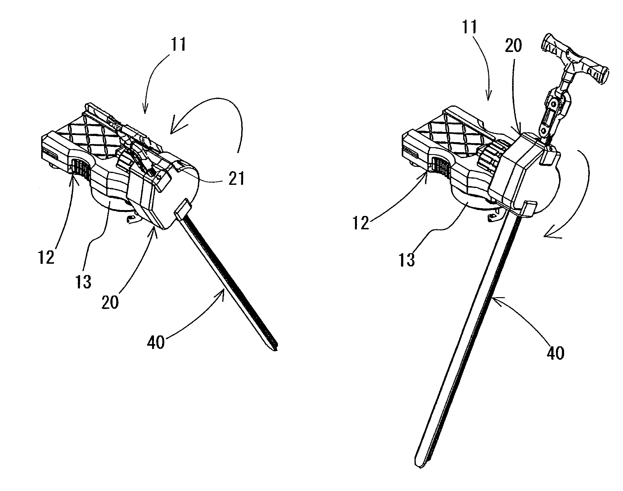
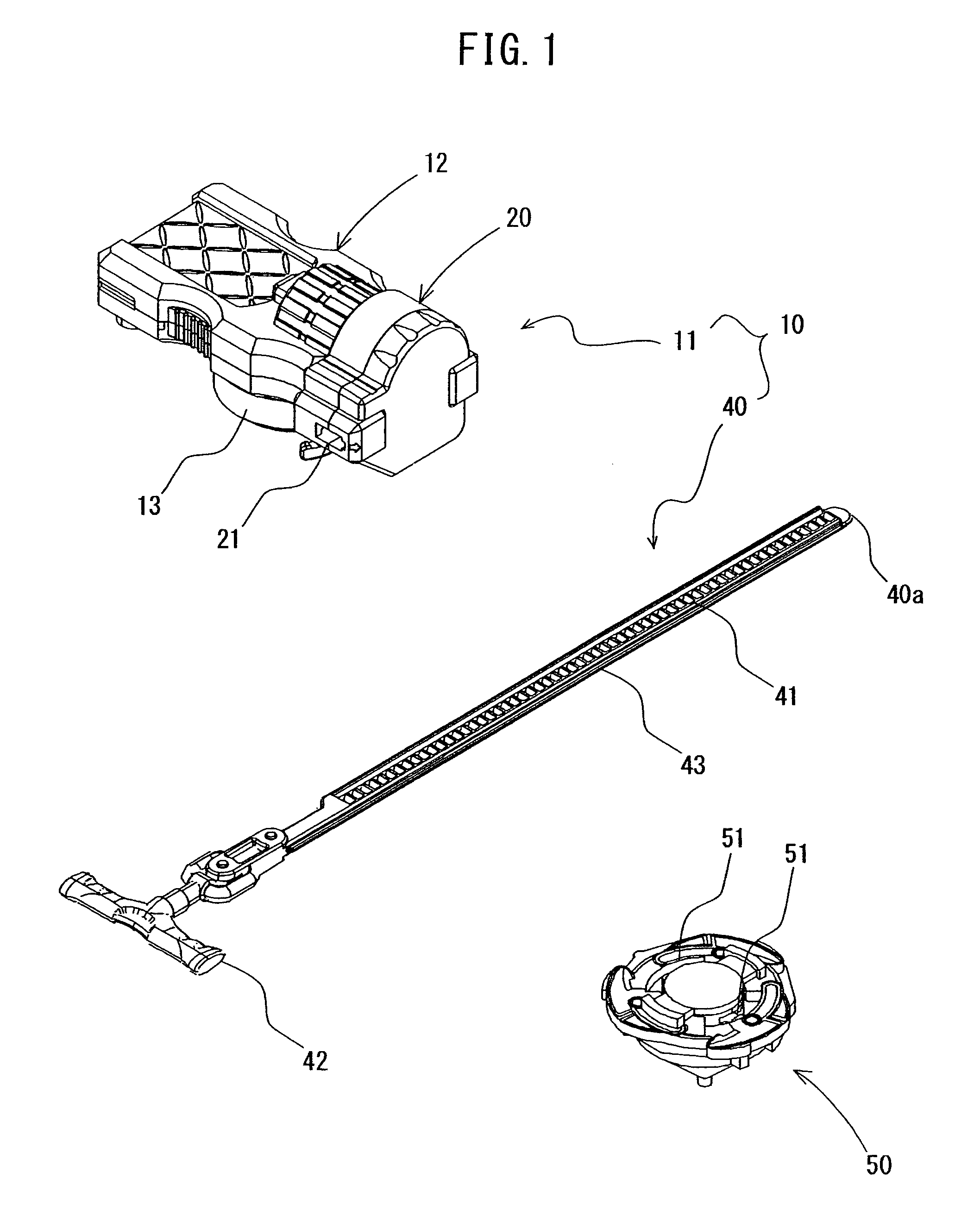
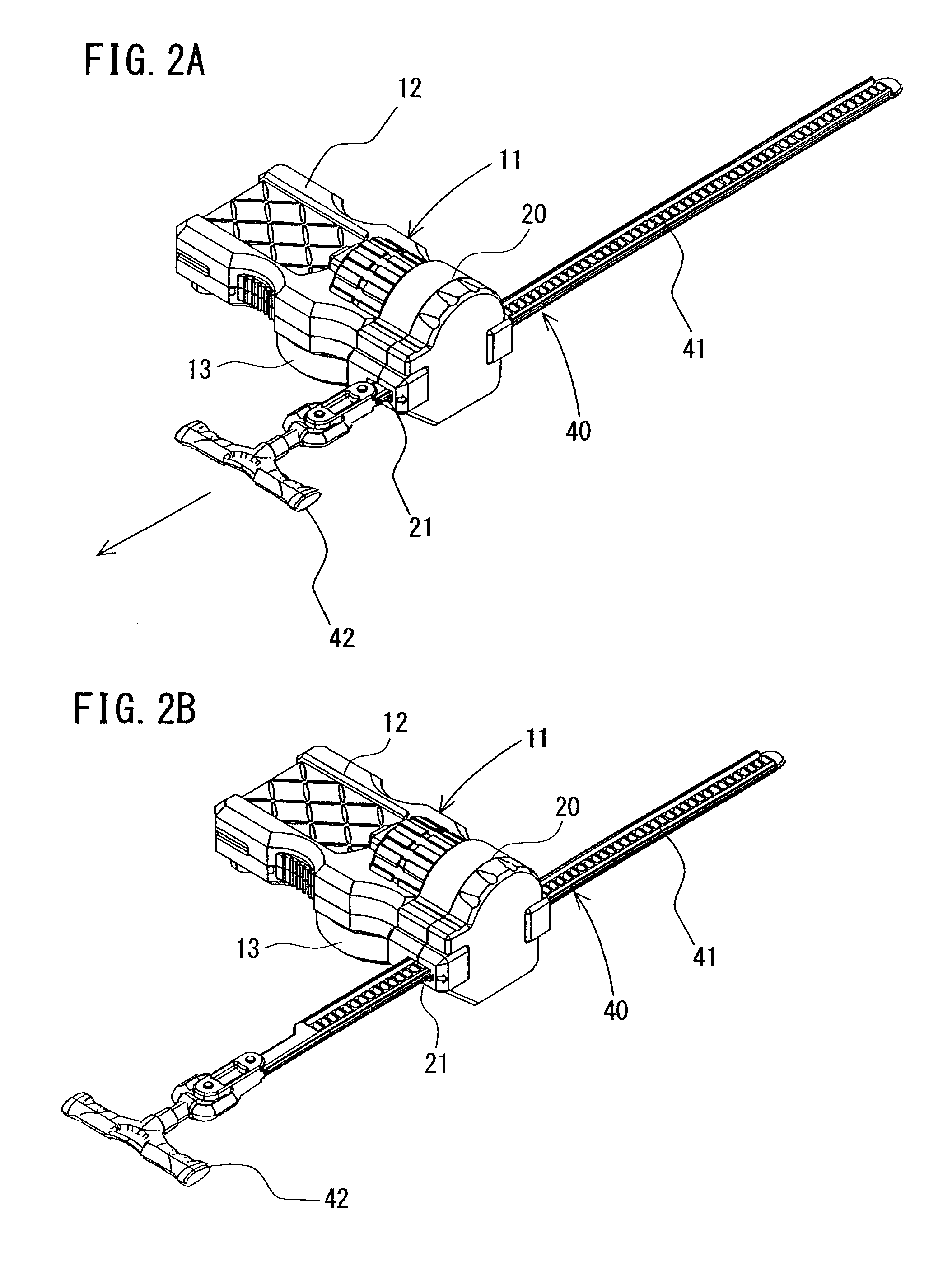
[0028]A spinner for a toy top according to an embodiment of the present invention is described with reference to the drawings. A spinner 10 for a toy top according to the present embodiment is constructed to launch a toy top 50 while imparting a rotational force to the toy top 50, and includes, as shown in FIG. 1, a rack belt 40 and a spinner main body 11 that has a rotating mechanism 30 operable therein, which will be described further below. The spinner main body 11 has an insertion hole 21 formed therein through which the rack belt 40 is inserted. In this spinner 10, as shown in FIGS. 2A and 2B, the rack belt 40 is inserted through the insertion hole 21 formed in the spinner main body 11 and then the rack belt 40 is quickly pulled out, so that the rotating mechanism 30 provided in the spinner main body 11 can be actuated to impart a rotational force to the toy top 50.

[0029]As shown in FIGS. 1, 2A and 2B, the rack belt 40 has teeth of a rack gear 41 formed on a surface thereof to ...


PUM


Abstract

A spinner for a toy top enables a launching position of a toy top to be easily set and held in place even when a rack belt is vigorously pulled out. The spinner includes an elongated rack belt having a rack gear, and a spinner main body formed with an insertion hole through which the rack belt is inserted. The spinner main body includes a toy top mounting part rotatably provided on one surface thereof. Inside the spinner main body, a rotating mechanism that is actuated by pulling out the rack belt to impart a rotational force to the toy top mounting part is provided. The rack belt can be inserted into and pulled out from the insertion hole in a same direction as an axis of rotation of the toy top mounting part.

Description

CROSS-REFERENCE TO RELATED APPLICATIONS[0001]This application claims the benefit under 35 U.S.C. §119 of Japanese Utility Model Application No. 2010-6647 filed on Oct. 6, 2010, which is hereby incorporated by reference in its entirety in this application.BACKGROUND OF THE INVENTION[0002]1. Field of the Invention[0003]The present invention relates to a spinner for a toy top, and in particular, to a spinner for a toy top for launching a toy top while imparting a rotational force to the toy top by inserting a rack belt therein and pulling it out therefrom.[0004]2. Description of the Related Art[0005]Conventionally, a spinner for a toy top which launches a toy top through an operation of pulling out a rack belt has been known.[0006]For example, Japanese Utility Model Registration No. 3160658, corresponding to U.S. Ser. No. 12 / 895,283 filed Sep. 30, 2010, discloses a spinner for a toy top which is so constructed that after a toy top is mounted on a toy top mounting part of a spinner main...

Claims


Application Information

Patent Timeline
Patent Type & Authority Patents(United States)
IPC IPC(8): A63H1/00
CPCA63H1/12
Inventor HORIKOSHI, KENJIMAEDA, TAKEAKI
Owner TOMY CO LTD
Why Eureka
Try Eureka