Plug-in connection multi-segment rotary shaft structure

a rotary shaft and plug-in connection technology, which is applied in the direction of wing accessories, instruments, manufacturing tools, etc., can solve the problems of limited rotational freeness of the pivot devices nearly positioned in the same central line, affecting the rotational freeness of the pivot devices, and the inability to smoothly rotate and open or close the upper cover of the electronic device. , to achieve the effect of greatly enhancing the rotational freeness of the electronic devi

Active Publication Date: 2014-05-13
FIRST DOME
View PDF17 Cites 56 Cited by
  • Summary
  • Abstract
  • Description
  • Claims
  • Application Information

AI Technical Summary

Benefits of technology

[0007]It is therefore a primary object of the present invention to provide a plug-in connection multi-segment rotary shaft structure applicable to

Problems solved by technology

The axes of the shafts of the two pivot devices often fail to coincide with each other.
Moreover, the rotational freeness of the pivot devices nearly po

Method used


Image

  • Plug-in connection multi-segment rotary shaft structure
  • Plug-in connection multi-segment rotary shaft structure
  • Plug-in connection multi-segment rotary shaft structure

Examples


Embodiment Construction

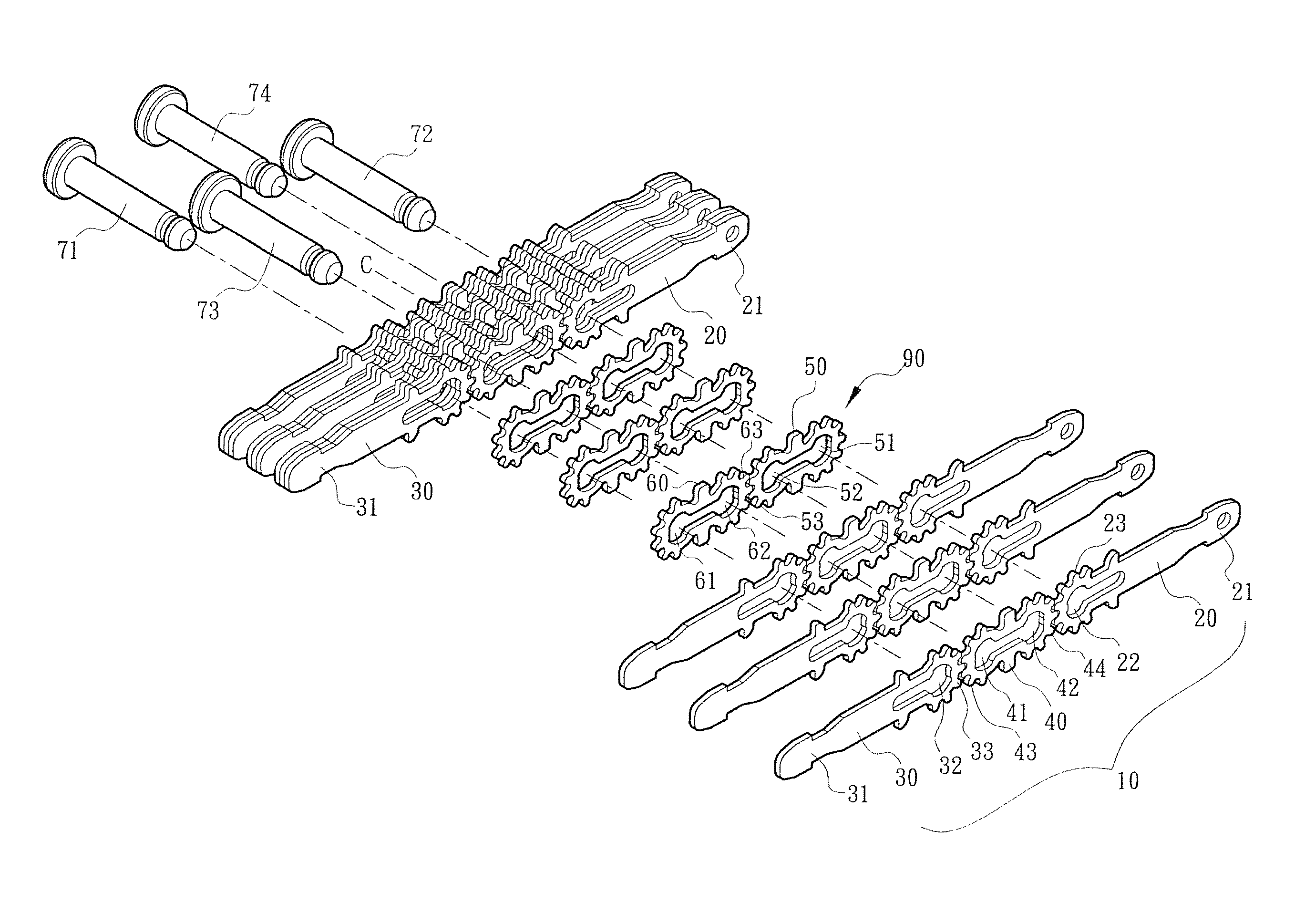
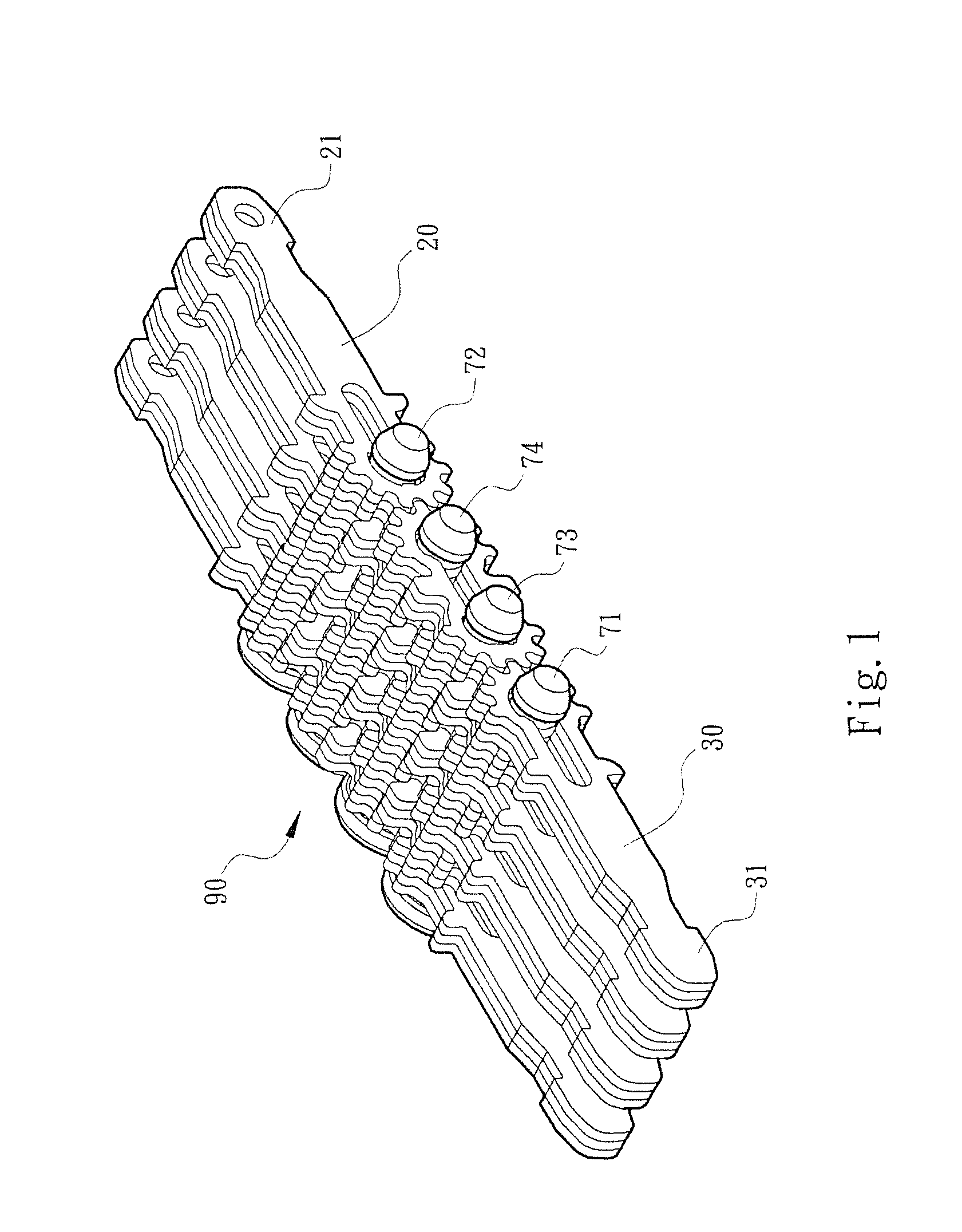
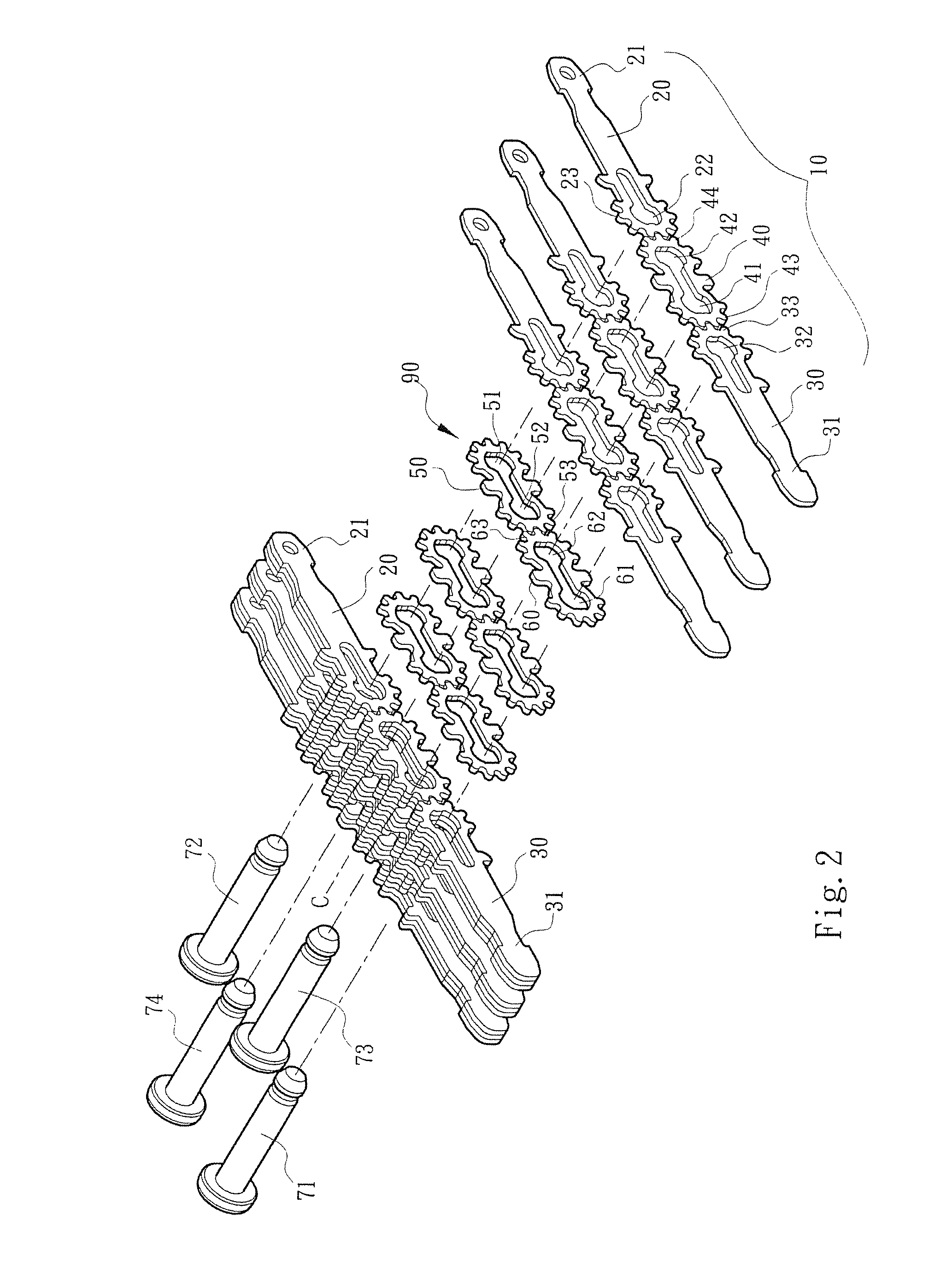
[0025]Please refer to FIGS. 1 to 3. The plug-in connection multi-segment rotary shaft structure of the present invention includes multiple driving joint assemblies 10 and multiple driven joint assemblies 90 (referring to FIG. 3). The driving joint assemblies 10 and the driven joint assemblies 90 are side by side arranged and combined with each other by means of multiple shaft pins to form the plug-in connection multi-segment rotary shaft structure.

[0026]In order to facilitate illustration of the connection relationship between the components, a direction toward the central line C of FIG. 2 will be referred to as “inward”, while a direction away from the central line C will be referred to as “outward” hereinafter.

[0027]The driving joint assembly 10 at least includes a first joint plate 20, a second joint plate 30 opposite to the first joint plate 20 and a middle link plate assembly 40. Two ends of the first and second joint plates 20, 30 are respectively formed with outward plugs 21,...


PUM


Abstract

A plug-in connection multi-segment rotary shaft structure includes a driving joint assembly and a driven joint assembly. The driving joint assembly includes two opposite joint plates and a middle link plate assembly engaged therebetween. The driven joint assembly is disposed between the joint plates and includes two driven plates. Opposite inward ends of the driven plates are formed with synchronous driving sections drivingly engaged with each other. Inward ends of the opposite joint plates are connected with the outward ends of the driven plates. Outward ends of the joint plates are formed with plugs. Outward ends of the middle link plate assembly are connected with the inward ends of the driven plates. The driving joint assembly and driven joint assembly are connected and combined, whereby the joint plates can be freely rotated around multiple rotational centers.

Description

BACKGROUND OF THE INVENTION[0001]1. Field of the Invention[0002]The present invention relates generally to a plug-in connection multi-segment rotary shaft structure, and more particularly to a multi-segment rotary shaft structure applicable to an electronic device. The multi-segment rotary shaft structure has multiple rotational centers so that the rotational freeness of the electronic device is enhanced and two ends of the electronic device can be more smoothly rotated and opened or closed.[0003]2. Description of the Related Art[0004]With a notebook or the like electronic device taken as an example, the notebook is generally composed of a base seat as a system end and an upper cover as a display end. The base seat and the upper cover are pivotally connected with each other via a pivot device, whereby the upper cover can be lifted open around the pivot device for use or reversely closed onto upper surface of the base seat. The pivot device is quite important in that it not only serv...

Claims


Application Information

Patent Timeline
IPC IPC(8): E05D15/00E05D7/00
CPCE05D7/00G06F1/1681E05Y2900/606Y10T16/541E05D3/122E05Y2201/71E05D15/00Y10T16/5474Y10T16/547E05D5/04
Inventor HSU, AN SZUDAI, WAY HAN
Owner FIRST DOME
Why Eureka
Try Eureka