Fastener for document folder

a document folder and fastener technology, applied in the field of pressing means, can solve the problems of inconvenient sorting of documents, document order is usually out of order, and other hands may be wounded, and achieve the effect of simple structure, safety and practicality

Active Publication Date: 2014-05-13
LEUNG MING FUK
View PDF13 Cites 2 Cited by
  • Summary
  • Abstract
  • Description
  • Claims
  • Application Information

AI Technical Summary

Benefits of technology

[0003]The objective of the invention is to overcome the defects in the prior art and provide a fastener for a document folder, wherein when the fastener is opened, no hand is required for holding the fastener; and when the fastener is closed, no hand is required for pulling a hook body, and thus hands are prevented from being wounded due to clamping.
[0017]The invention has the advantages that: the invention relates to a fastener for a document folder, which comprises a base plate, a hook bracket and torsion springs, wherein the front end of the base plate is extended upwards and curled to form a bending section; a slot is formed by the surrounding of the bending section; rotating shafts on two sides of the front end of the hook bracket are respectively arranged at two ends of the inside of the slot; the torsion springs are respectively sleeved on the rotating shafts on two sides of the front end of the hook bracket; one ends of the torsion springs are fixed on the rotating shafts and the other ends of the torsion springs are fixed on the base plate; end sections of the rotating shafts are bent upwards to form retaining sections; clamp holes engaged with the retaining sections and used for fastener opening are formed on the front of the bending section; when the hook bracket is turned up along with the rotation of the rotating shafts until the retaining sections of the rotating shafts rotate to the clamp holes, top ends of the retaining sections are extended out of the clamp hooks and the retaining sections are clamped with the clamp holes; and the upper part of the bending section is movably connected with a slider which is used for fastener closing and can slide along the surface of the bending section. As the retaining sections are formed on the rotating shafts of the hook bracket and the corresponding clamp holes are formed on the bending section, the two processes of fastener opening and fastener closing of the hook bracket are independent of each other. After the fastener is opened through the hook bracket, the retaining sections are clamped in the clamp holes, and thus the hook bracket cannot revolve due to the torsional force of the torsion springs. Moreover, as the slider is arranged on the retaining sections and the pressure fingers of the slider are over against the retaining sections, when the fastener is required to be closed, only the pressure fingers of the slider are required for being pressed down to press the retaining sections into the clamp holes, and then the hook bracket will rotate counterclockwise under the action of the torsional force of the torsion springs until the fastener is closed. The fastener for the document folder has the advantages of simple structure and safety and practicality.

Problems solved by technology

Therefore, when the state of fastener opening is maintained, a user can only use one hand to hold the fastener and the other hand to put documents in order, and thus the documents are usually out of order.
When the fastener is closed, if the hand for holding the fastener is abruptly let go, a hook bracket of the fastener may revolve abruptly, and thus the other hand may be wounded due to the impact and holding of the hook bracket.
The fastener for the document folder has the disadvantages that: when the fastener is opened, manpower is required for holding the fastener, and thus the sorting of the documents is inconvenient; and when the fastener is closed, the hands may be wounded.

Method used


Image

  • Fastener for document folder
  • Fastener for document folder
  • Fastener for document folder

Examples


embodiment

[0029]

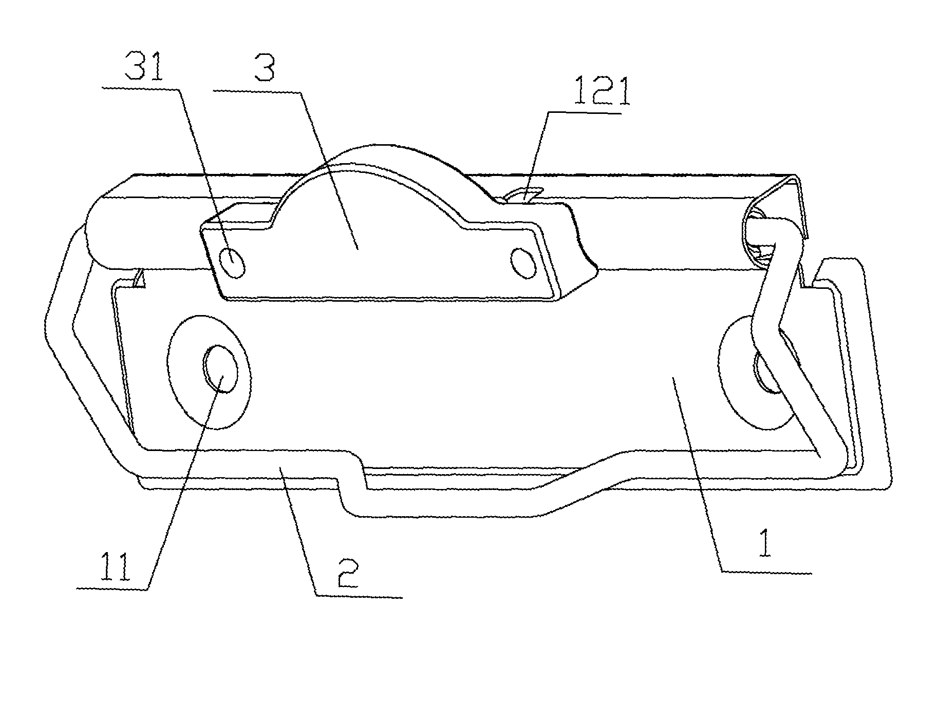
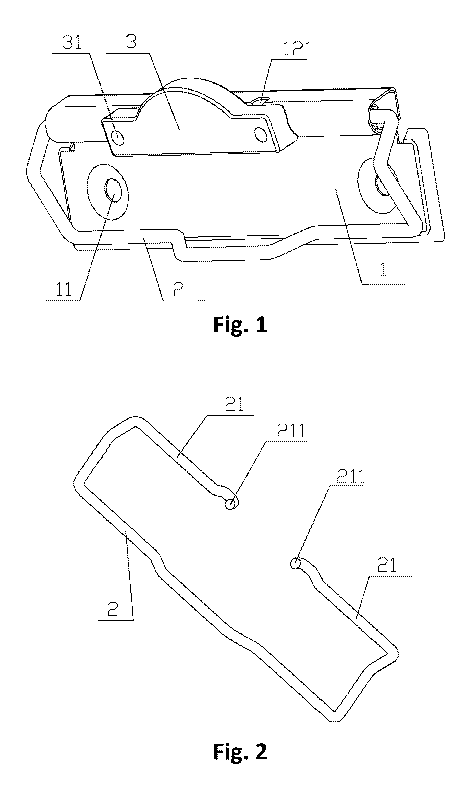
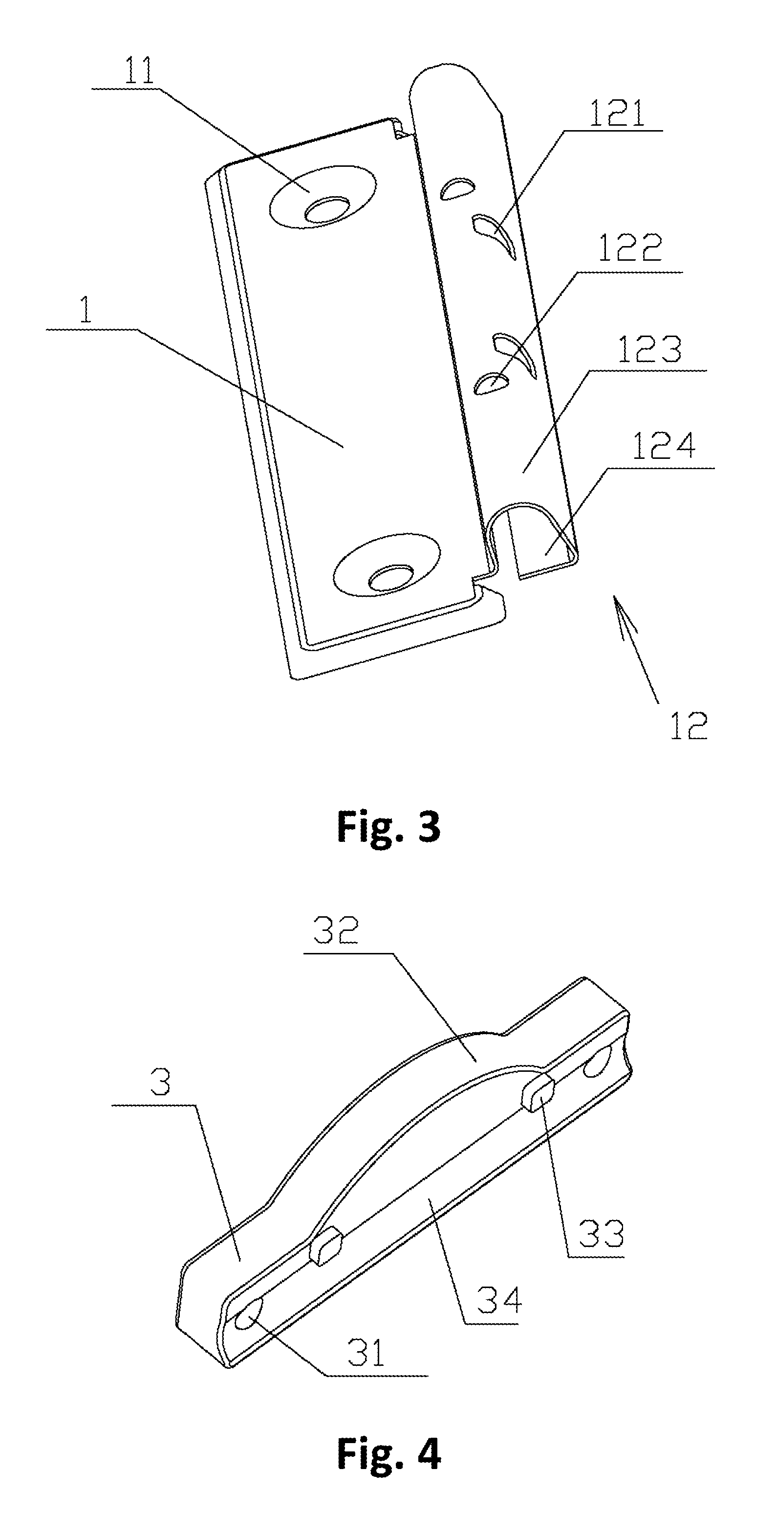
[0030]As illustrated in FIGS. 1 to 10, the invention relates to a fastener for a document folder, which comprises a base plate 1, a hook bracket 2 and torsion springs 5, wherein the front end of the base plate 1 is extended upwards and curled to form a bending section 12; a slot is formed by the surrounding of the bending section 12; rotating shafts 21 on two sides of the front end of the hook bracket 2 are respectively arranged at two ends of the inside of the slot; the torsion springs 5 are respectively sleeved on the rotating shafts 21 on two sides of the front end of the hook bracket 2; one ends of the torsion springs 5 are fixed on the rotating shafts 21 and the other ends of the torsion springs 5 are fixed on the base plate 1 or the bending section 12; end sections of the rotating shafts 21 are bend upwards to form retaining sections 211; clamp holes 121 engaged with the retaining sections 211 and used for fastener opening are formed on the front of the bending section 1...


PUM


Abstract

A fastener for a document folder includes a base plate, a hook bracket and torsion springs. The front end of the base plate is extended upwards and curled to form a bending section. A slot is formed by the surrounding of the bending section. Rotating shafts on two sides of the front end of the hook bracket are respectively arranged at two ends of the inside of the slot. The torsion springs are respectively sleeved on the rotating shafts on two sides of the front end of the hook bracket. Some ends of the torsion springs are fixed on the rotating shafts and the other ends of the torsion springs are fixed on the base plate. End sections of the rotating shafts are bent upwards to form retaining sections. Clamp holes are engaged with the retaining sections and used for fastener opening formed on the front of the bending section.

Description

FIELD OF THE INVENTION[0001]The invention relates to the technical field of clamping means, in particular to a fastener for a document folder.BACKGROUND OF THE INVENTION[0002]Document folders are widely used in office and study and frequently used in work. For example, the Chinese utility model Apl. No. 200720052528.9 titled “Document Folder” is provided. When a fastener for the document folder is opened, manpower is required for fastener opening and the state of fastener opening must be maintained. When the fastener for the document folder is closed, manpower is usually required for auxiliary and slow closing of the fastener so as to avoid the risk of pinching hand. In order to increase the clamping force of the fastener to the document folder, the torsional force of torsion springs fixed on rotating shafts of the fastener is larger. Therefore, when the state of fastener opening is maintained, a user can only use one hand to hold the fastener and the other hand to put documents in ...

Claims


Application Information

Patent Timeline
Patent Type & Authority Patents(United States)
IPC IPC(8): B42F9/00
CPCB42F9/001Y10T24/202Y10T24/206Y10T24/203
Inventor LEUNG, MING-FUK
Owner LEUNG MING FUK
Why Eureka
Try Eureka