System for bending a metallic strip

a technology of a system and a metal strip, which is applied in the direction of metal-working feeding devices, positioning devices, shaping tools, etc., can solve the problems of replacement of bending tools, considerable wear of bending tools, so as to achieve the effect of simple production

Active Publication Date: 2014-05-13
PROFORM
View PDF5 Cites 0 Cited by
  • Summary
  • Abstract
  • Description
  • Claims
  • Application Information

AI Technical Summary

Benefits of technology

[0016]When in the rest condition, the tools are always near the guide aperture, positioned alongside the latter. This position, in addition to favouring rapid performance of the bending operation, is particularly suitable for replacement of the tools. In fact, when the tools have to be replaced, the blocking means can be set to release both the worn tools. The new tools can thus be easily positioned and, by setting the blocking means to the locking position, they are ready to proceed with the strip bending operations. The blocking means for locking and releasing the bending tools preferably include brackets that can be rotated around an axis perpendicular to the feed direction of the strip. The blocking means can be operated in various ways, for example by using pneumatic or electric actuators or similar.
[0022]The simplicity of the solution proposed by the present invention furthermore allows one single motor to be used to simultaneously drive both the hubs.

Problems solved by technology

This results in considerable wear of the bending tools and therefore the need to replace the tools fairly frequently to ensure the necessary working accuracy.
The effects of wear on the tool are therefore considerable if strips have to be produced with particularly narrow bending angles.
The known systems described above are particularly complex from the mechanical point of view and, consequently, replacement of the bending tools can be particularly time-consuming, thus affecting productivity.

Method used


Image

  • System for bending a metallic strip
  • System for bending a metallic strip
  • System for bending a metallic strip

Examples


Embodiment Construction

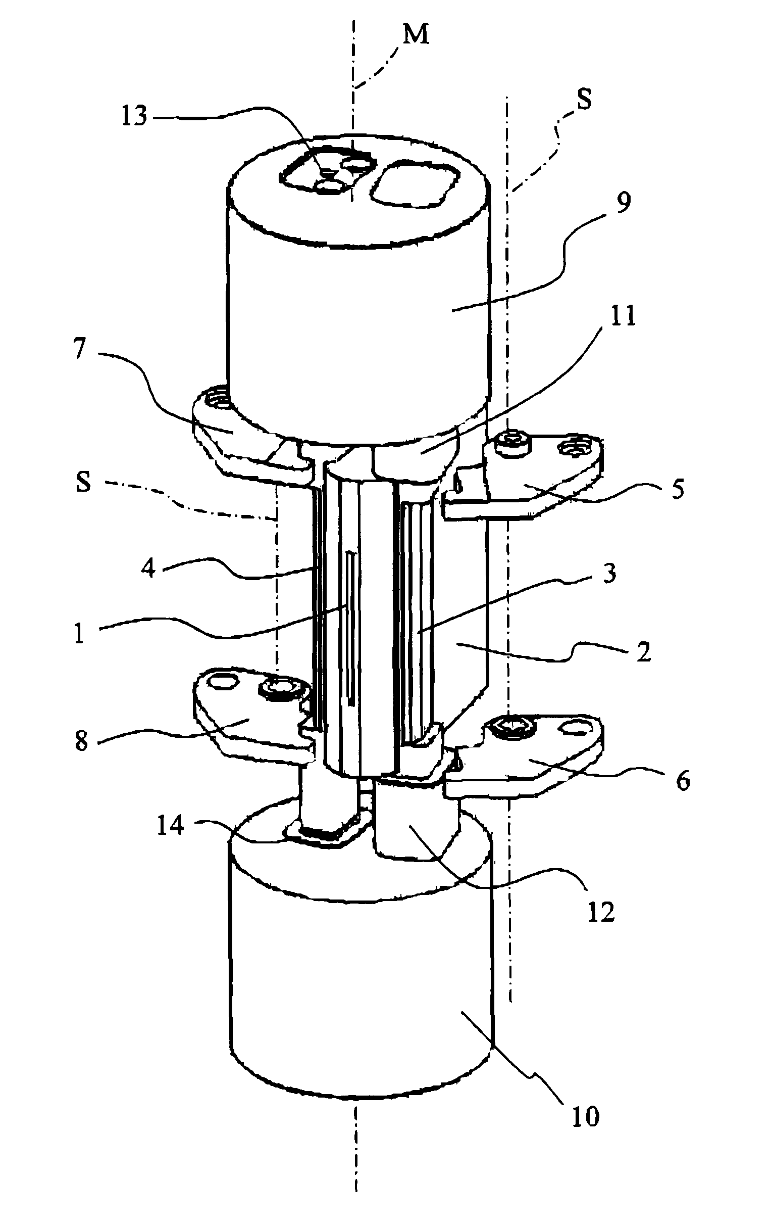
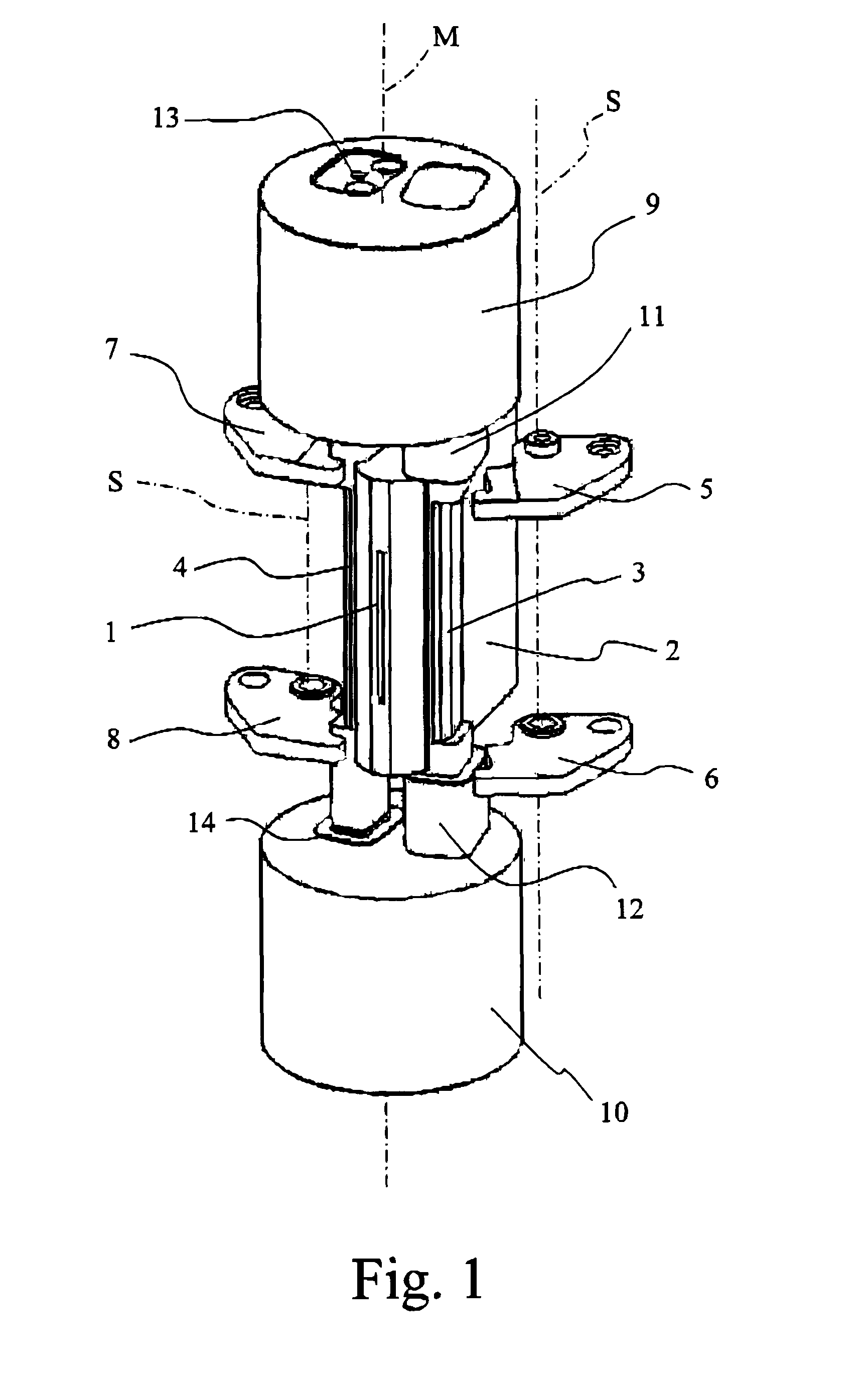
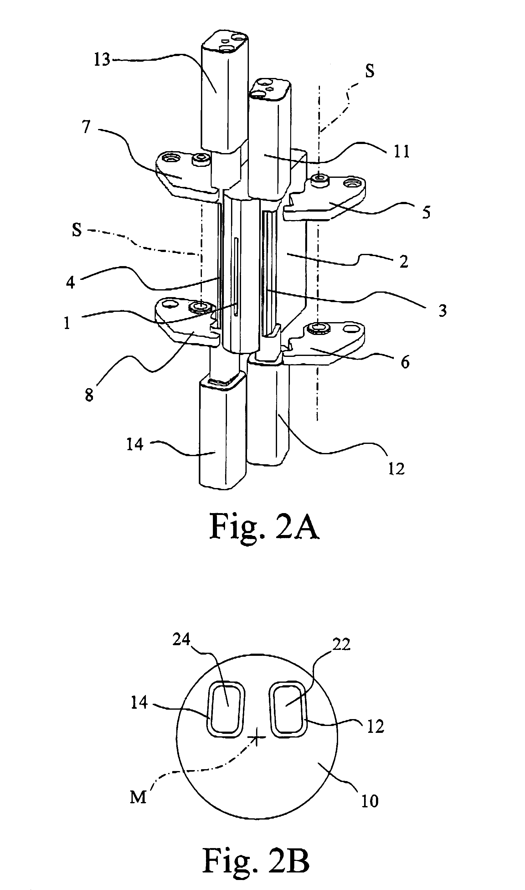
[0037]With reference first to FIG. 1, the device for bending metallic strips according to the invention is illustrated as it is about to perform the bending operation in one of the two directions.

[0038]The device includes a guide aperture 1 positioned vertically and arranged at the end of the feed section 2 via which the strip to be processed (not shown) is fed forward to the point where the bend is required and temporarily locked during the bending step. Although FIG. 1 illustrates a configuration of the device in which the guide aperture 1 and the feed section 2 are oriented in a vertical direction, the device can be installed with guide aperture oriented in a horizontal direction.

[0039]The bending tools 3 and 4 are retained alongside the guide aperture 1 by means of four brackets 5, 6, 7 and 8, two for each tool, which can rotate around axes S perpendicular to the feed direction of the strip. The brackets 5-8 are movable in pairs between a position in which the tools 3 and 4 are ...


PUM

PropertyMeasurementUnit
rotation angleaaaaaaaaaa
lengthaaaaaaaaaa
pre-set angleaaaaaaaaaa

Abstract

A device and a process are described for bending a metallic strip (W) by means of bending tools (3, 4) which can rotate around a common axis (M) near a guide aperture (1) through which the metallic strip to be bent is fed. Controllable blocking means (5-8) are provided to lock the bending tools in positions mutually alongside the guide aperture when they are in the rest condition, and to release at least one of the bending tools in the operating condition in which the bending is performed.

Description

[0001]This application is the U.S. national phase of International Application No. PCT / IT2008 / 000348, filed 27 May 2008, which designated the U.S. the entire contents of which is hereby incorporated by reference.FIELD OF THE INVENTION[0002]The present invention concerns a system for bending a metallic strip and, in particular, a device and a process for the production of for die-cutting blades starting from a continuous metallic strip which is shaped via successive bending steps and undergoes a final shearing step.BACKGROUND OF THE INVENTION[0003]The devices known in the art for bending metallic strips, in particular those intended for the production of die-cutting blades, generally include a system for feeding the continuous metallic strip through a guide aperture, in the vicinity of which one or more bending tools are located. In the majority of cases two bending tools are provided, one to bend the strip to the right (or upwards, for example) and the other to bend the strip to the...

Claims


Application Information

Patent Timeline
Patent Type & Authority Patents(United States)
IPC IPC(8): B21D11/00
CPCB21D7/022B21D37/205B21D5/042
Inventor SPAIRANI, ROBERTOSPAIRANI, SECONDO
Owner PROFORM
Why Eureka
Try Eureka