
Four side bending system

A four-sided, bending machine technology, applied in the field of sheet metal processing equipment, can solve the problems of low manufacturing cost, inability to take into account production efficiency, product variety applicability and manufacturing cost, etc.

Active Publication Date: 2016-01-27
YINDU KITCHEN EQUIP
View PDF6 Cites 0 Cited by
  • Summary
  • Abstract
  • Description
  • Claims
  • Application Information

AI Technical Summary

Problems solved by technology

[0003] In order to overcome the shortcomings of the above existing sheet metal bending equipment that cannot take into account production efficiency, product variety applicability and manufacturing cost, the present invention provides a four-sided bending machine with high production efficiency, low manufacturing cost, suitable for multiple varieties, and simple maintenance. bending system

Method used


Image

  • Four side bending system
  • Four side bending system
  • Four side bending system

Examples


Embodiment 1

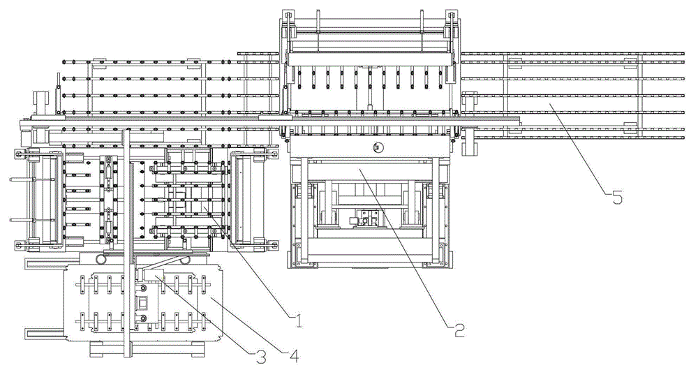
[0085] Embodiment 1: A four-sided bending system, the four-sided bending system is an L-type four-sided bending system, such as figure 1 As shown, it includes a first bending unit 1, a second bending unit 2 and a material transfer device 3. The first bending unit 1 is responsible for all bending processes of a group of opposite sides, and the second bending unit The bending unit 2 is responsible for all the bending processes of another group of opposite sides, and the material transfer device 3 is responsible for transferring the sheet material from the feeding station 4 to the first bending unit 1, and at the same time, the first bending unit 1. A group of parts with opposite sides folded is transferred to the second bending unit 2, and another group of parts with opposite sides folded by the second bending unit 2 is transferred to the unloading station 5. Complete the four-sided bending of the part.

[0086] The first bending unit 1 is as image 3 , including a fixed bendi...

Embodiment 2

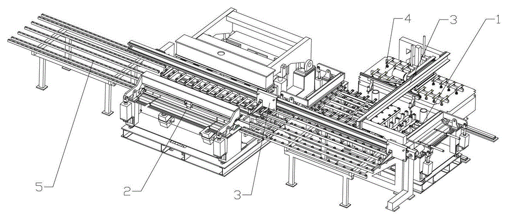
[0126] Embodiment 2: The four-side bending system of this embodiment adopts a straight-line four-side bending system, such as figure 2 As shown, the linear transfer device is as Figure 23 , comprising a frame 132, a loading station 133, a power unit 134, a first vacuum suction device 135, a second vacuum suction device 136, a pushing device 137 and a blanking station 138;

[0127] Described frame 132 is provided with power unit 134, the first vacuum suction device 135, the second vacuum suction device 136 and pushing device 137; Place on the workbench 8 of the first bending unit 1 from the feeding station 133, while the second vacuum suction device 136 sucks up the processed sheet from the workbench 8 of the first bending unit 1 from being placed to On the workbench 50 of the second bending unit 2, at the same time, the pushing device 137 pushes the processed sheet material of the second bending unit 2 from the second bending unit 2 to the blanking station 138, and then the...


PUM


Abstract

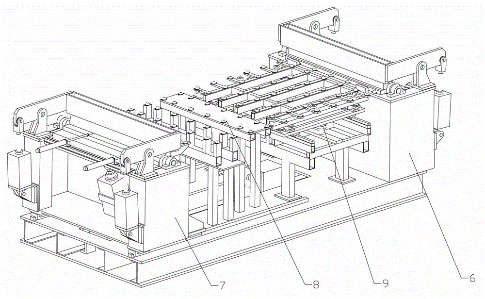
The invention relates to a four-side bending system comprising a first bending unit, a second bending unit and a material transferring device, wherein the first bending unit is used for completing the bending work of a group of opposite sides of a material to be bent; the second bending unit is used for completing the bending work of the other group of opposite sides of the material to be bent; and the material transferring device is used for shifting the material according to the process. The first bending unit comprises a first static bending machine, a first movable bending machine, a first working table and a first positioning part, wherein the first static bending machine and the first movable bending machine are oppositely placed on a main frame; and the working table and the positioning part are placed between the first static bending machine and the first movable bending machine. The second bending unit comprises a second static bending machine, a second movable bending machine, a second working table and a second positioning part, wherein the second static bending machine and the second movable bending machine are oppositely placed on the main frame; and the second working table and the second positioning part are placed between the second static bending machine and the second movable bending machine. The four-side bending system is relatively high in production efficiency, relatively low in manufacture cost and simple to maintain and is suitable for various productions.

Description

technical field [0001] The invention belongs to sheet metal processing equipment, in particular to a metal plate bending equipment Background technique [0002] Bending the four sides of the metal sheet is widely used in household refrigerators, commercial freezers, electrical cabinets, metal cabinets and other manufacturing industries. Now similar to those used by these manufacturing companies, the bending equipment with a high degree of automation can be divided into two categories, one It is a special line for sheet metal bending, and one is the multilateral bending center of the Italian company Salvagnini. The sheet metal bending special line is equipped with multiple special machines according to one kind of bending parts. Each special machine is responsible for one bending edge of the part. It is suitable for mass production of a single variety and high production efficiency, but it can only process one kind of part or the same series of parts. , poor adaptability, no...

Claims


Application Information

Patent Timeline
Patent Type & Authority Patents(China)
IPC IPC(8): B21D19/00
CPCB21D5/045
Inventor 周俊杰李征宇
Owner YINDU KITCHEN EQUIP
Learn More