
Camera module group combined method and camera module group

The technology of a camera module and a combination method, which is applied in the field of photography, can solve the problems of fragile components, poor compatibility between the lens unit and the photosensitive unit, and time-consuming combination, so as to achieve good compatibility, avoid repeated disassembly operations, and improve combination efficiency effect

Inactive Publication Date: 2008-12-24
HONG FU JIN PRECISION IND (SHENZHEN) CO LTD +1
View PDF0 Cites 3 Cited by
  • Summary
  • Abstract
  • Description
  • Claims
  • Application Information

AI Technical Summary

Problems solved by technology

[0004] 1) The camera module combination method needs to go through the process of "combination detection, splitting and recombination", which is time-consuming and easy to damage components;
[0005] 2) Due to the separate correction of the locking surface or assembly surface, the corrected lens unit and photosensitive unit generally need to be paired one by one to meet the coaxial condition, and the compatibility between the lens unit and photosensitive unit is poor

Method used


Image

  • Camera module group combined method and camera module group
  • Camera module group combined method and camera module group
  • Camera module group combined method and camera module group

Examples


Embodiment Construction

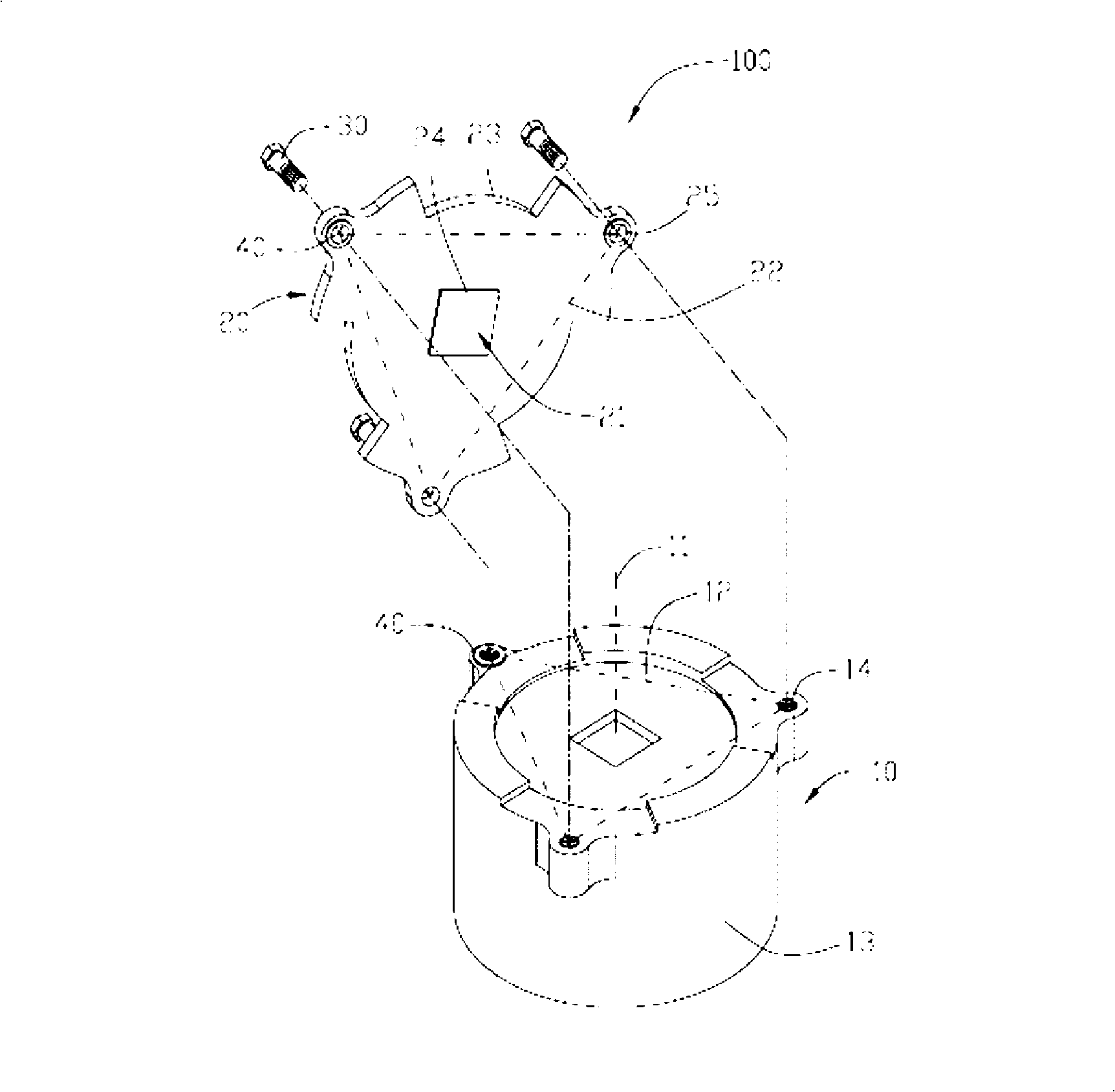
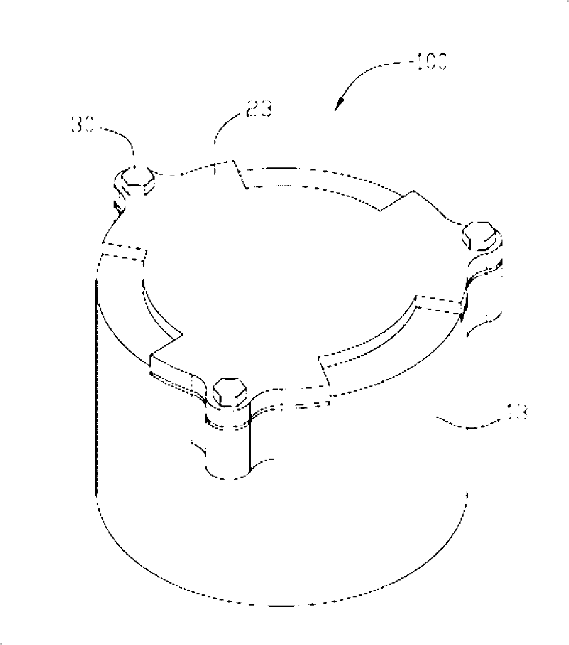
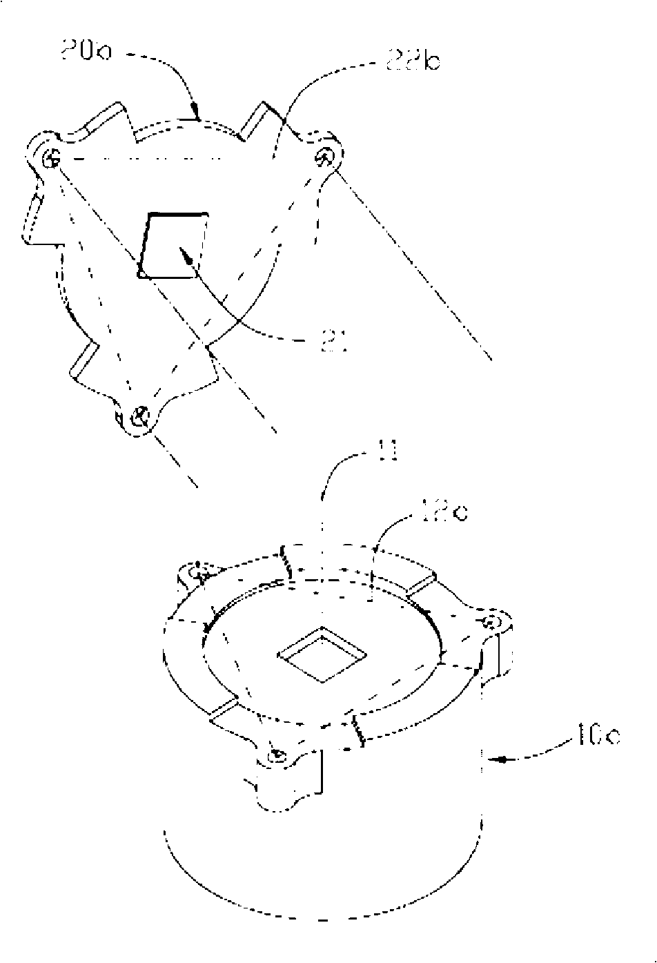
[0019] Please also see figure 1 and figure 2 , the camera module 100 of the preferred embodiment includes a lens unit 10 and a photosensitive unit 20 . The lens unit 10 has an optical axis 11 and a locking surface 12 , the optical axis 11 is perpendicular to the locking surface 12 . The photosensitive unit 20 has a photosensitive surface 21 and an assembly surface 22 , the assembly surface 22 is parallel to the photosensitive surface 21 and locked to the locking surface 11 .

[0020] Specifically, the lens unit 10 includes a lens barrel 13 and a lens group accommodated in the lens barrel 13 , a shutter mechanism, a focusing mechanism, etc. (not shown). The optical axis of the lens group is the optical axis 11 of the lens unit 10 . The end surface of the lens barrel 13 is provided with three screw holes 14 , and the edges of the three screw holes 14 form the locking surface 12 . The photosensitive unit 20 includes an assembly board 23 and an image sensor 24 disposed on the ...


PUM


Abstract

The invention provides a combination method of a camera module and the camera module obtained by the method. The combination method of the camera module is used for combining a lens unit and a photographic unit and comprises the steps as follows: whether the locking adhesion surface of the lens unit is vertical to an optical axis thereof or not is detected; if not vertical, the locking adhesion surface is corrected till the locking adhesion surface is vertical to the optical axis; whether the assembly surface of the photographic unit is parallel to a photosurface or not is detected; if not parallel, the assembly surface is corrected till the assembly surface is parallel to the photosurface; and the assembly surface which is vertical to the optical axis is locked and adhered to the locking adhesion surface which is parallel to the photosurface. The combination method of the camera module respectively detects and corrects the lens unit and the photographic unit and further combines the lens unit and the photographic unit after the correction, thereby avoiding the possible splitting action from damaging elements after the combination. In addition, the combination method can avoid the repeated demolition and rotation operations and enhance the combination efficiency. The lens unit and the photographic unit which are obtained by utilizing the combination method of the camera module have great universality.

Description

technical field [0001] The invention relates to camera technology, in particular to a method for combining camera modules and a camera module. Background technique [0002] The camera module includes a lens unit and a photosensitive unit. The lens unit has an optical axis and a locking surface, the photosensitive unit has a photosensitive surface and an assembly surface, and the assembly surface is locked to the locking surface. When the camera module is assembled, the components are first assembled into a lens unit and a photosensitive unit, and then the lens unit and the photosensitive unit are combined into a camera module. [0003] In order to ensure the image quality, the camera module needs to meet the condition: the optical axis of the lens unit is perpendicular to the photosensitive surface (hereinafter referred to as the coaxial condition). However, limited by the component production process and assembly process, the directly combined camera module may not meet t...

Claims


Application Information

Patent Timeline
Patent Type & Authority Applications(China)
IPC IPC(8): G02B7/02G03B17/02H04N5/225
CPCG02B7/022G03B3/04G03B17/28Y10T29/49764Y10T29/49769Y10T29/4978Y10T29/49778H04N23/57
Inventor 陈盈智
Owner HONG FU JIN PRECISION IND (SHENZHEN) CO LTD
Learn More