Al technical title is built by PatSnap Al team. It summarizes the technical point description of the patent document.
A technology of rotating machinery and worktable, applied in the field of foundry, can solve the problems of high labor intensity of workers, affecting the combination of sand cores, damage of sand cores, etc., and achieve the effects of improving combination efficiency, improving yield and convenient use.
Inactive Publication Date: 2016-05-11
贾雪松
View PDF0 Cites 3 Cited by
Summary
Abstract
Description
Claims
Application Information
AI Technical Summary
This helps you quickly interpret patents by identifying the three key elements:
Problems solved by technology
Method used
Benefits of technology
Problems solved by technology
[0002] In order to improve casting efficiency and meet the requirements of modern production, foundry enterprises mostly use hot core box core shooters to manufacture cores used in the casting process. Core shooters are widely used in the foundry machinery industry. The core made by the machine has the advantages of accurate size and smooth surface, so it is widely used in many foundry companies. In foundry production, after the core of the hot core box core shooting machine is completed, it is sometimes necessary to combine several sand cores. , in order to facilitate the combination of sand cores, sometimes it is necessary to rotate the sand cores at a certain angle. Now, the rotation of sand cores is generally carried out manually. This method not only has low production efficiency, but also has high labor intensity for workers, and manual methods are used. There is often a certain error in the angle of rotation, which may affect the combination of sand cores. Sometimes the sand cores will be damaged when rotating manually, resulting in a lot of waste products
Method used
Image
Click on the blue label to locate the original text in one second.
Reading with bidirectional positioning of images and text.
Examples
Embodiment 1
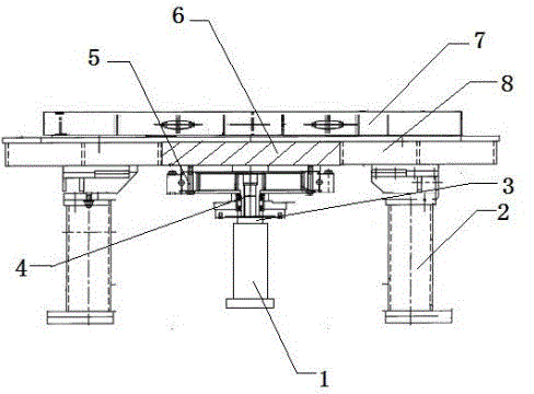
[0013] This embodiment provides an automated rotating machinery workbench, characterized in that: the automated rotating machinery workbench includes a hydraulic cylinder (1), a support column (2), a hydraulic piston (3), and a coupling (4) , fixed tooling (5), turntable (6), workbench (7), fixed chuck (8);
[0014] Wherein: a fixed chuck (8) is fixed on the supporting column (2), the fixed chuck (8) is a workbench (7), and the turntable (6) arranged in the workbench (7) and the fixed chuck (8) connection, the turntable (6) is connected to the driving device, the driving device includes the hydraulic cylinder (1), the hydraulic piston (3) and the coupling (4), the hydraulic piston (3) and the coupling (4) of the hydraulic cylinder (1) ) connection, the driving device is connected to the lower side of the turntable (6) through the fixed tooling (5), the fixed chuck (8) is circular, and the inner ring is provided with a slideway that matches the pulley of the turntable (6).
[...
PUM
Abstract
An automatic rotating mechanical worktable is characterized by comprising a hydraulic cylinder, supporting stand columns, a hydraulic piston, a coupler, a fixing tool, a rotating disc, a worktable body and a fixing chuck, wherein the fixing chuck is fixed to the supporting stand columns, the worktable body is arranged on the fixing chuck and connected with the rotating disc arranged in the fixing chuck, the lower side of the rotating disc is connected with a driving device, the driving device comprises the hydraulic cylinder, the hydraulic piston and the coupler, the hydraulic piston of the hydraulic cylinder is connected with the coupler, the driving device is connected to the lower side of the rotating disc through the fixing tool, the rotating disc is in a round cake shape, a sliding wheel is arranged on the outer edge of the rotating disc, the fixing chuck is in a ring shape, and a sliding track matched with the sliding wheel of the rotating disc is arranged on the inner ring of the fixing chuck. The automatic rotating mechanical worktable has the advantages that the structure is simple, use is convenient, the combination efficiency of sand cores can be effectively improved, and the labor intensity of workers can be effectively relieved; besides, by adopting a tabletop rotating device, the rotating angle of the sand cores can be guaranteed, the sand cores can be prevented from being damaged, the rate of finished products can be increased, and requirements of modernized production can be met.
Description
technical field [0001] The invention relates to the field of casting, in particular to a table-top rotating device for turning sand cores, and in particular to an automatic rotary mechanical workbench. Background technique [0002] In order to improve casting efficiency and meet the requirements of modern production, foundry enterprises mostly use hot core box core shooters to manufacture cores used in the casting process. Core shooters are widely used in the foundry machinery industry. The core made by the machine has the advantages of accurate size and smooth surface, so it is widely used in many foundry companies. In foundry production, after the core of the hot core box core shooting machine is completed, it is sometimes necessary to combine several sand cores. , in order to facilitate the combination of sand cores, sometimes it is necessary to rotate the sand cores at a certain angle. Now, the rotation of sand cores is generally carried out manually. This method not onl...
Claims
Application Information
Patent Timeline
Application Date:The date an application was filed.
Publication Date:The date a patent or application was officially published.
First Publication Date:The earliest publication date of a patent with the same application number.
Issue Date:Publication date of the patent grant document.
PCT Entry Date:The Entry date of PCT National Phase.
Estimated Expiry Date:The statutory expiry date of a patent right according to the Patent Law, and it is the longest term of protection that the patent right can achieve without the termination of the patent right due to other reasons(Term extension factor has been taken into account ).
Invalid Date:Actual expiry date is based on effective date or publication date of legal transaction data of invalid patent.