Window covering cutting machine

a cutting machine and window covering technology, applied in the field of window covering cutting devices, can solve the problems of not explaining how the blade was damaged, the damage of the cutting blade selected to cut vinyl, and the damage of the cutting blade or the window covering

Active Publication Date: 2014-05-13
LUMINO
View PDF13 Cites 4 Cited by
  • Summary
  • Abstract
  • Description
  • Claims
  • Application Information

AI Technical Summary

Benefits of technology

[0012]The controller may move the stops so that one stop is in the open position and the other stops are in the closed position. It should be understood that such an alignment of stops can prevent a user from mistakenly inserting the window covering work piece through the wrong openings.
[0021]The housing may further include at least one of a second opening and a third opening. For such embodiments, the cutting device may be configured to move to various other positions so that the cutting device blocks all but one opening or set of openings. For example, for embodiments that have a housing with a first, second and third opening, the cutting device may be configured to move from a default position, to a first position, a second position, or a third position. When in the default position, the cutting device may block the first opening, second opening and third opening. In the first position, the cutting device may block the second and third openings, but expose the first opening. In the second position, the cutting device may block the first and third openings and expose the second opening. In the third position, the cutting device may block the first and second openings, but expose the third opening. It should be appreciated that the cutting device can be configured to be maintained at its default position after the cutting mechanism is finished cutting the window covering or window covering work piece. Maintaining the cutting device in its default position prevents a user from mistakenly inserting a work piece to be cut by the cutting machine into the wrong opening and being cut by the wrong blade or other cutting device.

Problems solved by technology

Should this occur, the blade selected to cut vinyl can be damaged when it cuts the metal headrail.
Similar mistakes can occur for openings sized to receive other types of window coverings and can result in damage to the cutting blade or damage to the window covering.
When a blade or window covering is damaged, the retailer orders a replacement from the manufacturer of the cutting machine.
Typically, the retailer does not explain how the blade was damaged.
Indeed, a sales associate who damages the blade by using the wrong openings may not tell his or her supervisor of the mistake.
As a result, manufacturers of blind cutting machines have failed to recognize or appreciate the problem.
Yet, this problem can cause the retailer to incur significant costs in replacing blades and window coverings.

Method used


Image

  • Window covering cutting machine
  • Window covering cutting machine
  • Window covering cutting machine

Examples


first embodiment

[0045]Other embodiments of my cutting machine may use the blades of the cutting mechanism or part of the body of the cutting device to provide some of the functionality provided by the stops in the It should be understood that one or more end stops may not be included with such embodiments.

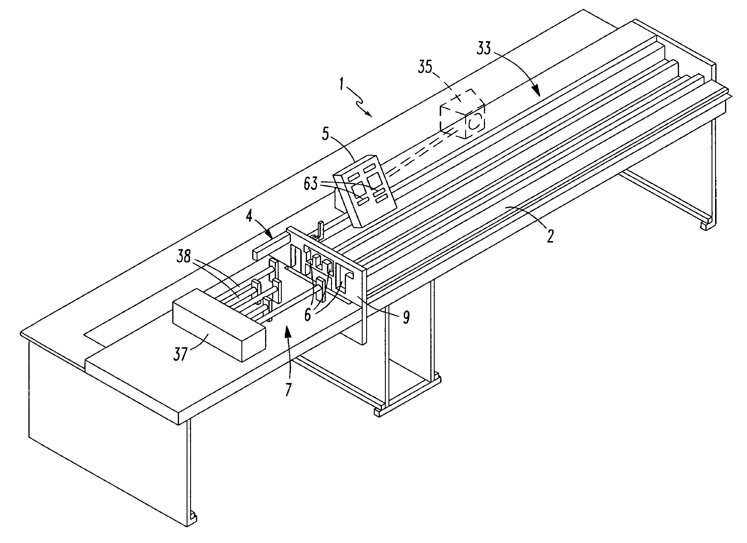
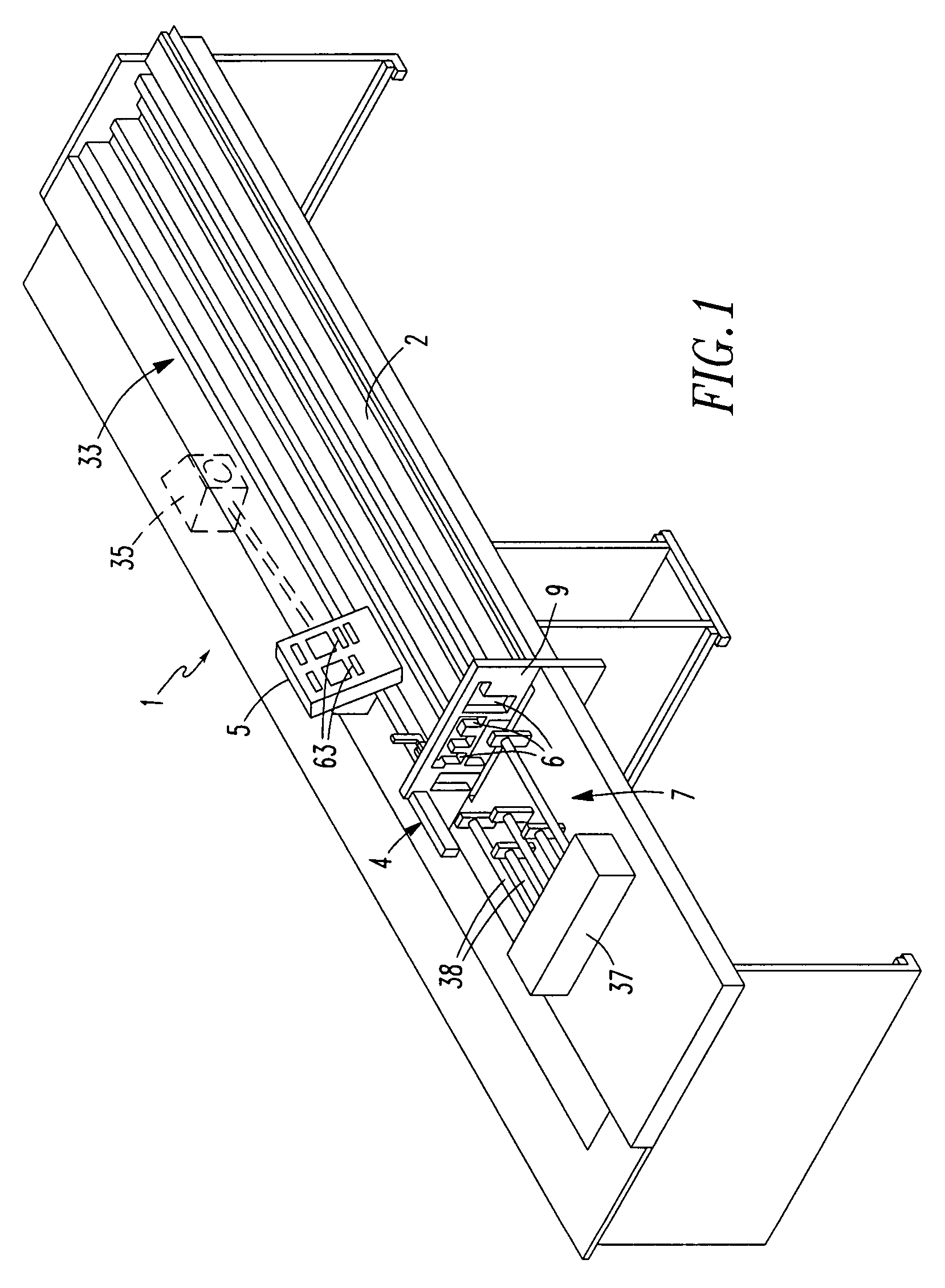
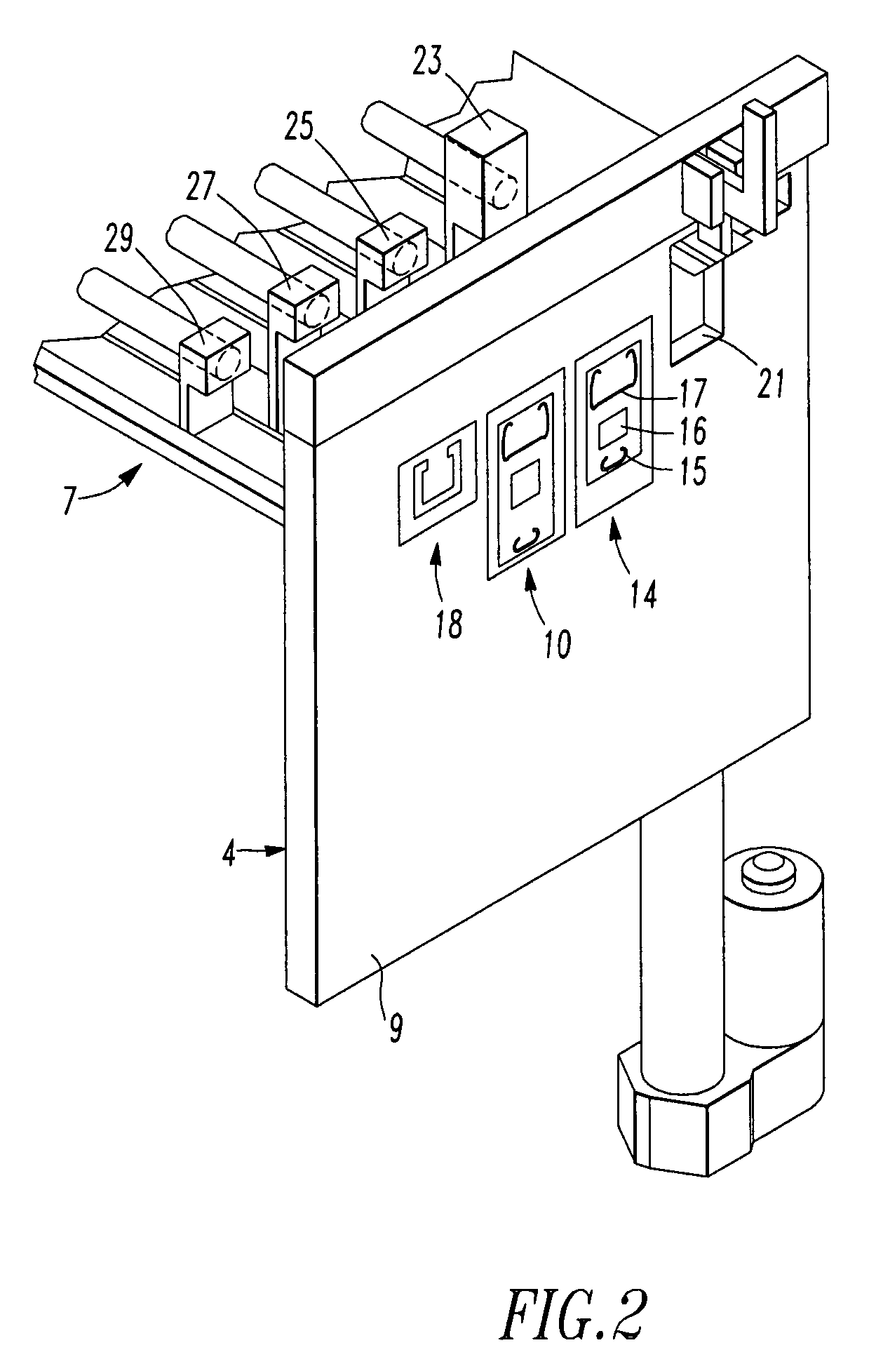
[0046]Referring to FIGS. 5, 6 and 7, an embodiment of my cutting machine 39 has a cutting mechanism 4 that has a housing 9 with sets of openings 10, 14, 18 and cutting device 40, which has a blade 41 adjacent an opening 42 that is sized and configured for alignment with each set of openings 10, 14, 18. The cutting device 40 is configured to move from a first position to various other positions prior to being actuated to make a cutting pass to cut a window covering or a window covering work piece that may extend through a set of openings with blade 41.

[0047]For example, cutting device 40 may move from the first position shown in FIG. 5 to a second position shown in FIG. 6 or a third position shown...

third embodiment

[0053]As shown in FIG. 9, my cutting machine has a cutting mechanism 4 that has blades 51, 52 and 53 aligned with respective set of openings 10, 14 and 18. The blades 51, 52 and 53 are configured to move from a closed position to an open position prior to cutting a portion of a window covering or a window covering work piece that may extend through the openings aligned with that blade.

[0054]As illustrated in FIG. 8, blades 51 and 52 are in their closed position and blade 53 is in its open position. Blade 53 may move from its open position to its closed position, which is shown by dotted line in FIG. 9, to cut a portion of a headrail. After a window covering work piece has been cut by blade 53, blade 53 is maintained in its closed position.

[0055]The cutting mechanism may also be configured to move blade 51 or blade 52 to their closed position in the event one or both of those blades were not at their closed position prior to attempting to cut down the headrail. Such movement of non-u...


PUM

PropertyMeasurementUnit
distanceaaaaaaaaaa
distanceaaaaaaaaaa
lengthaaaaaaaaaa

Abstract

A window covering cutting machine is disclosed that has a support table, a cutting mechanism adjacent the support table and a plurality of moveable stops moveably connected to at least one of the cutting mechanism and the support table. The support table has a surface on which at least a portion of a window covering work piece can be placed. The cutting mechanism has a housing with a plurality of openings sized to receive at least a portion of a window covering work piece. The cutting mechanism also has at least one cutting device configured to cut portions of a window covering that extend through any of the openings. One stop is aligned with each opening and is independently moveable relative to the housing and the other stops.

Description

FIELD OF INVENTION[0001]The present invention relates to window covering cutting devices.BACKGROUND OF THE INVENTION[0002]Home centers and other window covering retailers purchase window coverings in stock sizes from blind manufacturers and offer those stock window coverings for sale. Retailers often have cutting machines capable of cutting the stock window coverings. The cutting machines permit the retailer to cut the stock window covering for a customer so it may fit within window openings that have dimensions smaller than the stock window covering. Examples of such cutting machines are disclosed in U.S. Pat. Nos. 5,799,557, 5,927,172, 6,761,099 and U.S. Patent Publication No. 2007 / 0000363.[0003]A retailer will usually determine the amount of a stock window covering to cut based upon the difference in the dimensions of the stock window covering and the dimensions of the window opening in which the window covering will be mounted. The dimensions of a particular window opening are n...

Claims


Application Information

Patent Timeline
Patent Type & Authority Patents(United States)
IPC IPC(8): B23D23/00
CPCB23D31/00E06B9/266B23D33/10B23D23/00Y10T83/412Y10T83/7613Y10T83/404
Inventor KOLLMAN, MICHAEL
Owner LUMINO
Why Eureka
Try Eureka