Flat cable deflection device and installation kit for an electrical installation with circuit integrity in case of fire

a technology of circuit integrity and deflection device, which is applied in the direction of electrical equipment, external conductors, conductors, etc., can solve the problems of functional breakdown, shortening of cable strands, and losing insulation capacity of insulation cables, and achieves the effect of facilitating the cylindrical deflection elemen

Active Publication Date: 2014-05-13
WOERTZ
View PDF29 Cites 5 Cited by
  • Summary
  • Abstract
  • Description
  • Claims
  • Application Information

AI Technical Summary

Benefits of technology

[0005]The present invention relates to a flat cable deflection device with circuit integrity in case of a fire. It relates to a cylindrical cable deflection element made from fire resistant insulating material and a support for the cylindrical deflection element made from fire resistant material wherein the support is offset from the cylindrical deflection element so that it facilitates that the cylindrical deflection element is enveloped by the flat cable without touching the support.

Problems solved by technology

After some time the strand insulations of the cable lose their insulation capability under the flame effect and the strands of the cable short out.
This means a functional breakdown.
Typical cables do not comply with circuit integrity requirements of this type since the strand insulation can melt off or burn off rather quickly under fire influence and a short circuit can then occur through conductors contacting one another.
Generally obtaining higher circuit integrity durations is technically complex.

Method used


Image

  • Flat cable deflection device and installation kit for an electrical installation with circuit integrity in case of fire
  • Flat cable deflection device and installation kit for an electrical installation with circuit integrity in case of fire
  • Flat cable deflection device and installation kit for an electrical installation with circuit integrity in case of fire

Examples


Embodiment Construction

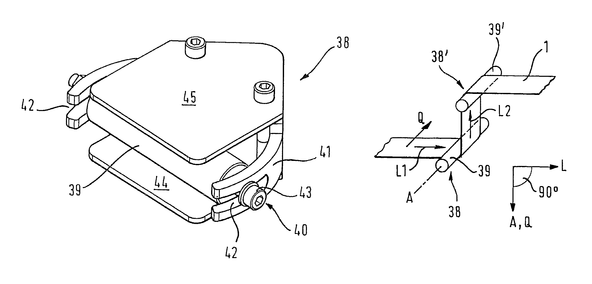
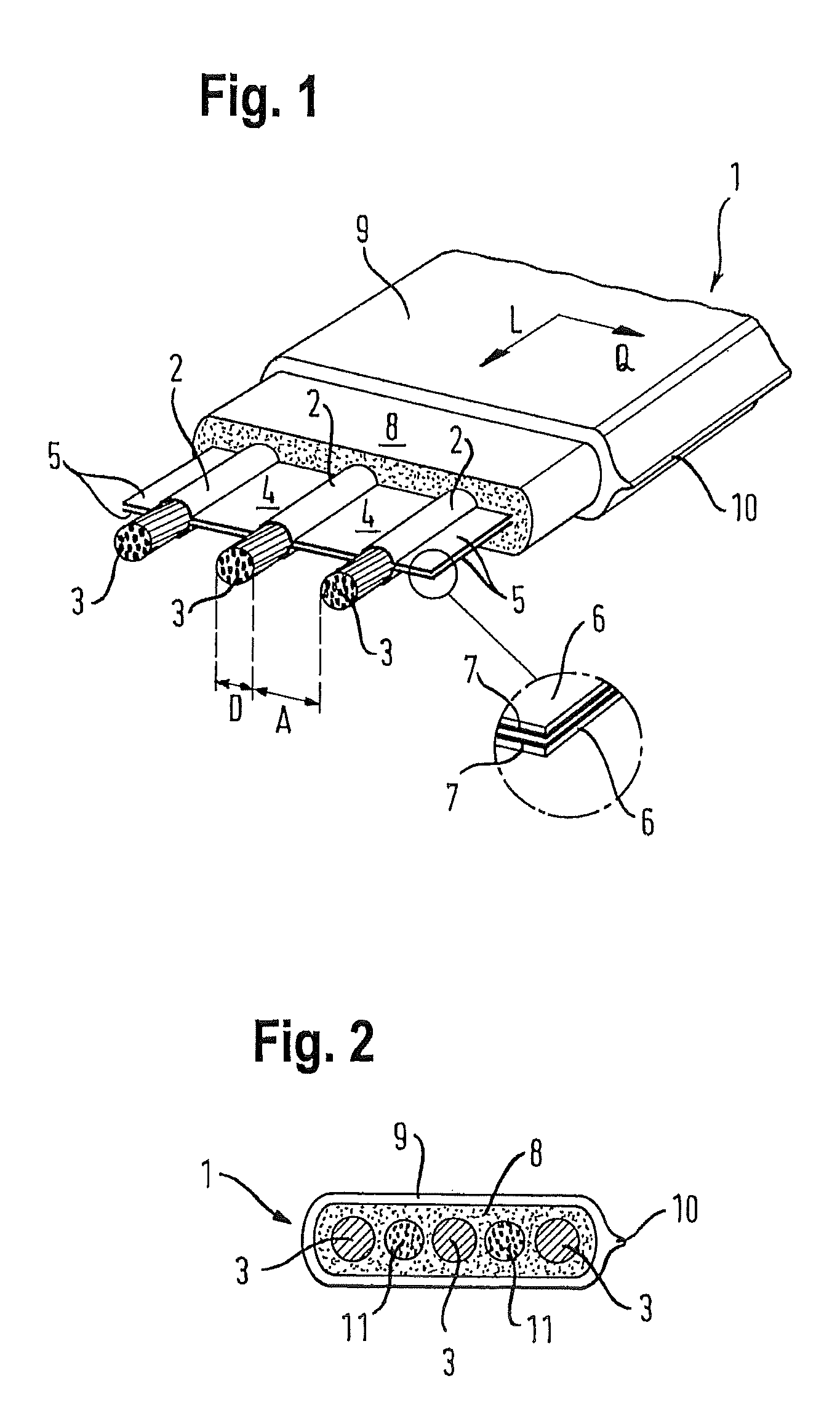
[0082]The terms “longitudinal cable direction” and “transversal cable direction” are illustrated in the FIGURES through direction arrows “L” or “Q”.

[0083]The flat cable illustrated in an exemplary manner in FIG. 1 is designated for single phase AC power and accordingly includes three high power current strands 2 (phase conductor, ground conductor and protective conductor). Each of the high power strands 2 is formed by a strand conductor 3 which is directly encased by a fire resistant insulating layer, this means without the strand insulation, that is annular in cross section as will be described infra in more detail. The strand conductors 3 extend parallel adjacent to one another in one plane and thus the center plane of the flat cable 1. The distance A between two strand conductors 3 is two times the diameter D of the strand conductors 3 in FIG. 1. In other embodiments the ratio ND is greater than e.g. 2.5 and 3.

[0084]In the center plane between the strand conductors 3 fire resista...


PUM

PropertyMeasurementUnit
envelopment angleaaaaaaaaaa
temperatureaaaaaaaaaa

Abstract

A flat cable deflection device with circuit integrity in case of a fire including a cylindrical cable deflection element made from fire resistant insulating material; and a support for the cylindrical cable deflection element made from fire resistant material. The support is offset from the cylindrical cable deflection element so that the support facilitates enveloping the cylindrical cable deflection element with a flat cable without the support contacting the flat cable. An electrical installation including at least one flat cable deflection device; at least one flat cable including plural high power current strands extending parallel adjacent to one another in a plane, where the flat cable runs over the deflection device and changes its direction at the deflection device, wherein the transversal cable direction in front and after the deflection device extends horizontally, and wherein the flat cable envelops the cylindrical cable deflection element at least partially.

Description

FIELD OF THE INVENTION[0001]The invention relates to a flat cable deflection device and installation kit for an electrical installation with circuit integrity in case of fire.BACKGROUND OF THE INVENTION[0002]In larger buildings, traffic structures like e.g. tunnels and ships evacuation times can be 30 minutes or more. Therefore these structures are typically equipped with electrical emergency devices which have to be supplied with electrical energy at least during the evacuation time period in order to facilitate an evacuation. These are e.g. smoke extraction blowers, emergency lighting and placards, etc.[0003]The suitability of an electrical installation for power supply also under the effect of a fire is designated as circuit integrity. Circuit integrity is defined by different standards. E.g. cables are being loaded with a voltage according to the standard IEC 60331-11 / -21 / -23 / -25 and exposed to a temperature greater than 750° C. for 90 to 180 minutes under the effect of a flame....

Claims


Application Information

Patent Timeline
Patent Type & Authority Patents(United States)
IPC IPC(8): H01B7/06
CPCH02G3/0412H02G3/30
Inventor ONODI, TAMAS
Owner WOERTZ
Why Eureka
Try Eureka