
Methods and systems for distributed diagnostic reasoning

a distributed diagnostic and reasoning technology, applied in error detection/correction, testing/monitoring control systems, instruments, etc., can solve the problems of cumbersome performance or significant modification costs, high complexity of cbm systems, and inability to solve problems in proportion to the cost of developing solutions, etc., to facilitate data flow

Inactive Publication Date: 2014-05-13
HONEYWELL INT INC
View PDF128 Cites 3 Cited by
  • Summary
  • Abstract
  • Description
  • Claims
  • Application Information

AI Technical Summary

Benefits of technology

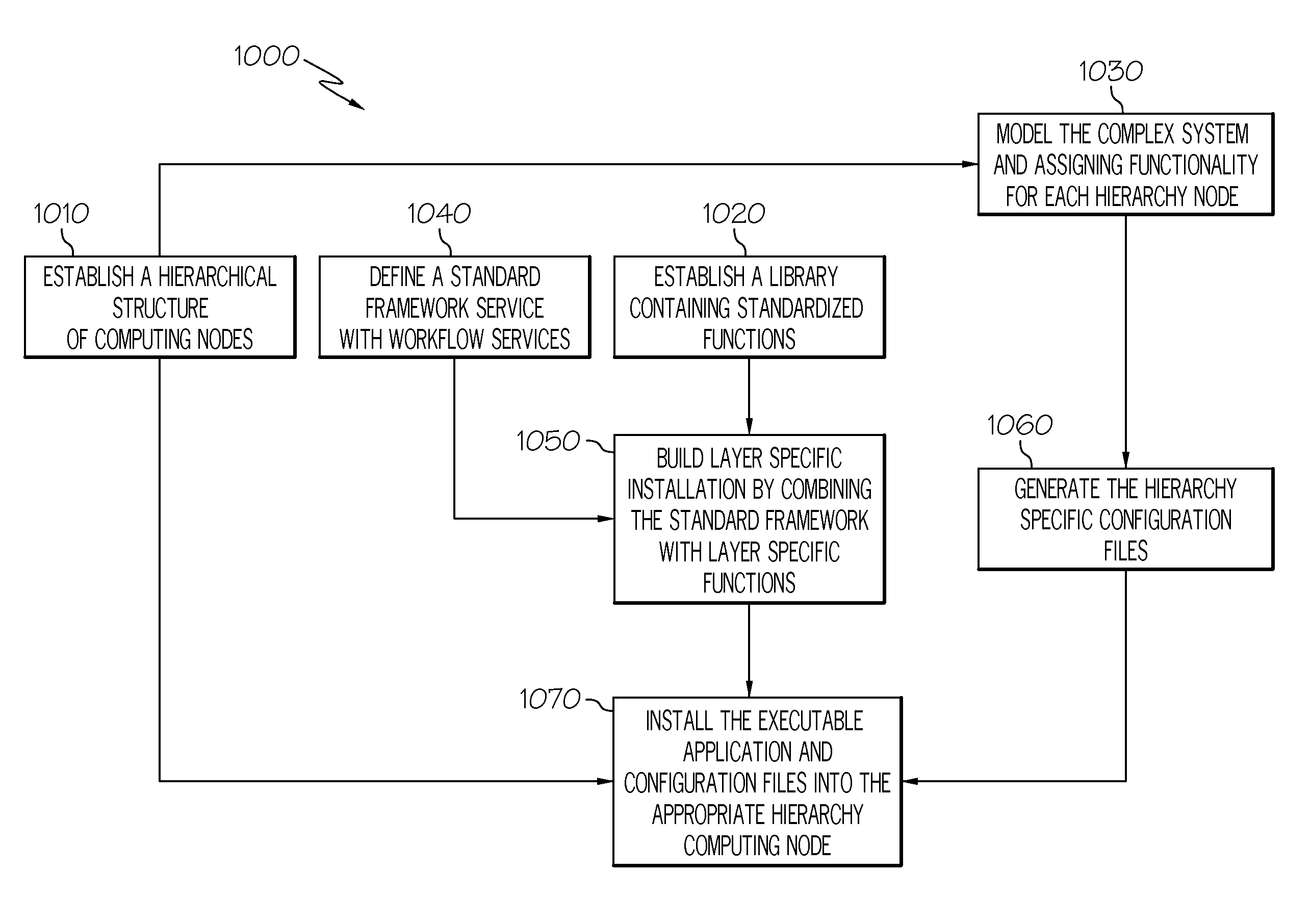
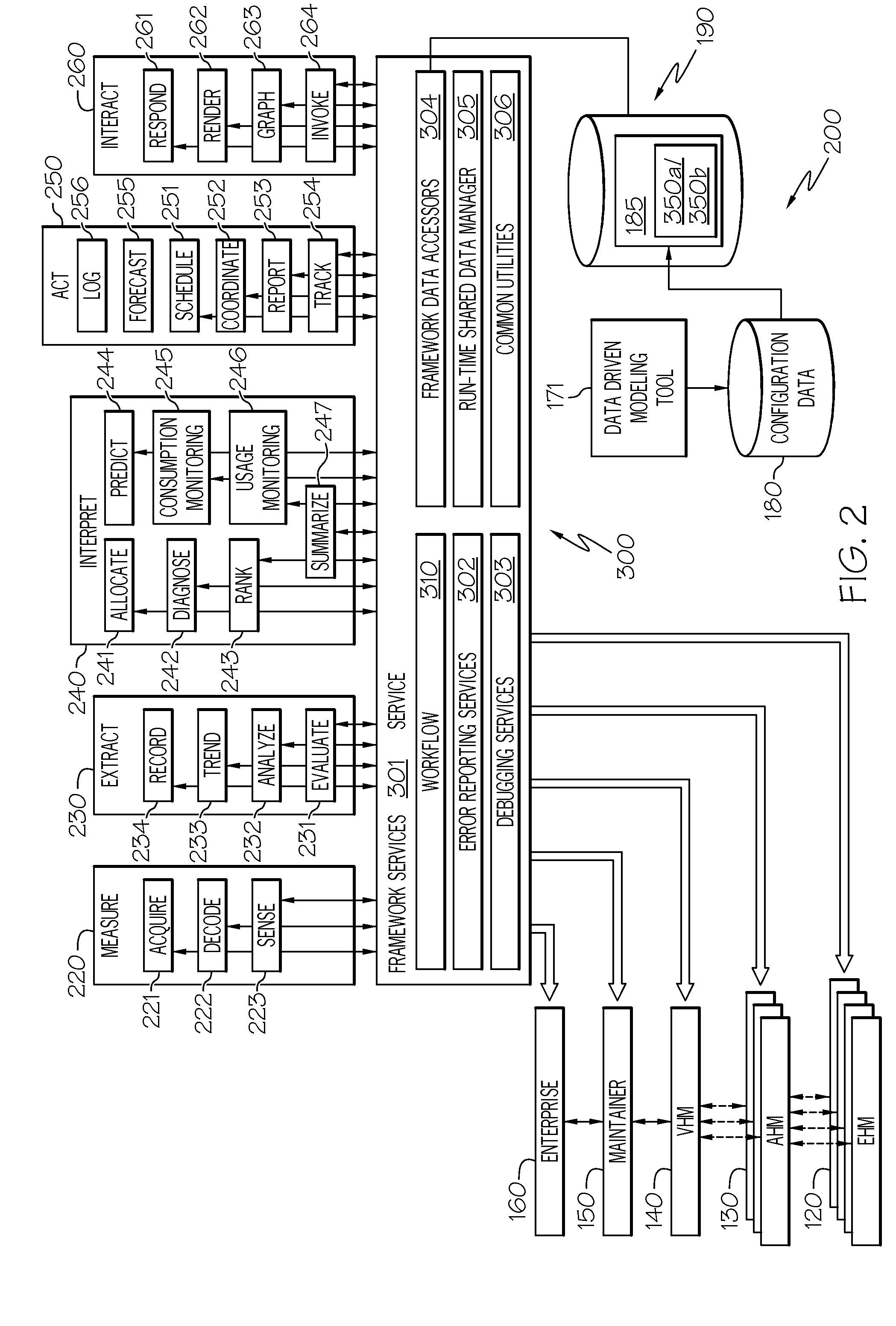
[0009]A method is provided for distributed diagnostic reasoning for a subsystem of a complex system. The method comprises establishing a computing node monitoring the operation of a component of a complex system, wherein the computing node includes a processor and a memory and populating at least one of the processor and the memory of the computing node with one or more standardized executable application modules (SEAM) and a workflow service; wherein the one or more SEAMS are configured not be unable to communicate directly with each other. The method further comprises creating a configuration file to form a distributed diagnostic reasoner (DDR) in conjunction with the one or more standardized executable application modules (SEAM) and a workflow service associated with the component, the DDR also comprising static data associated with a fault condition, installing the configuration file in the computing node for execution by the processor; and initializing the one or more SEAMS, the configuration file and the workflow service, wherein the workflow service facilitates data flow between the one or more SEAMS and the static data associated with a fault condition resident in the configuration file.
[0010]A computer readable storage media (CRSM) resident within a computing node is provided that contains instructions that when executed perform acts of distributed diagnostic reasoning for a subsystem of a complex system. The instructions include populating at least one of a processor and a memory of the computing node with one or more standardized executable application modules (SEAMs) and a workflow service; wherein the one or more SEAMS are unable to communicate directly with each other. The instructions further include installing the configuration file in the computing node for execution by the processor; and initializing the one or more SEAMS, the configuration file and the workflow service, wherein the workflow service facilitates data flow between the one or more SEAMS and the static data associated with a fault condition resident in the configuration file.

Problems solved by technology

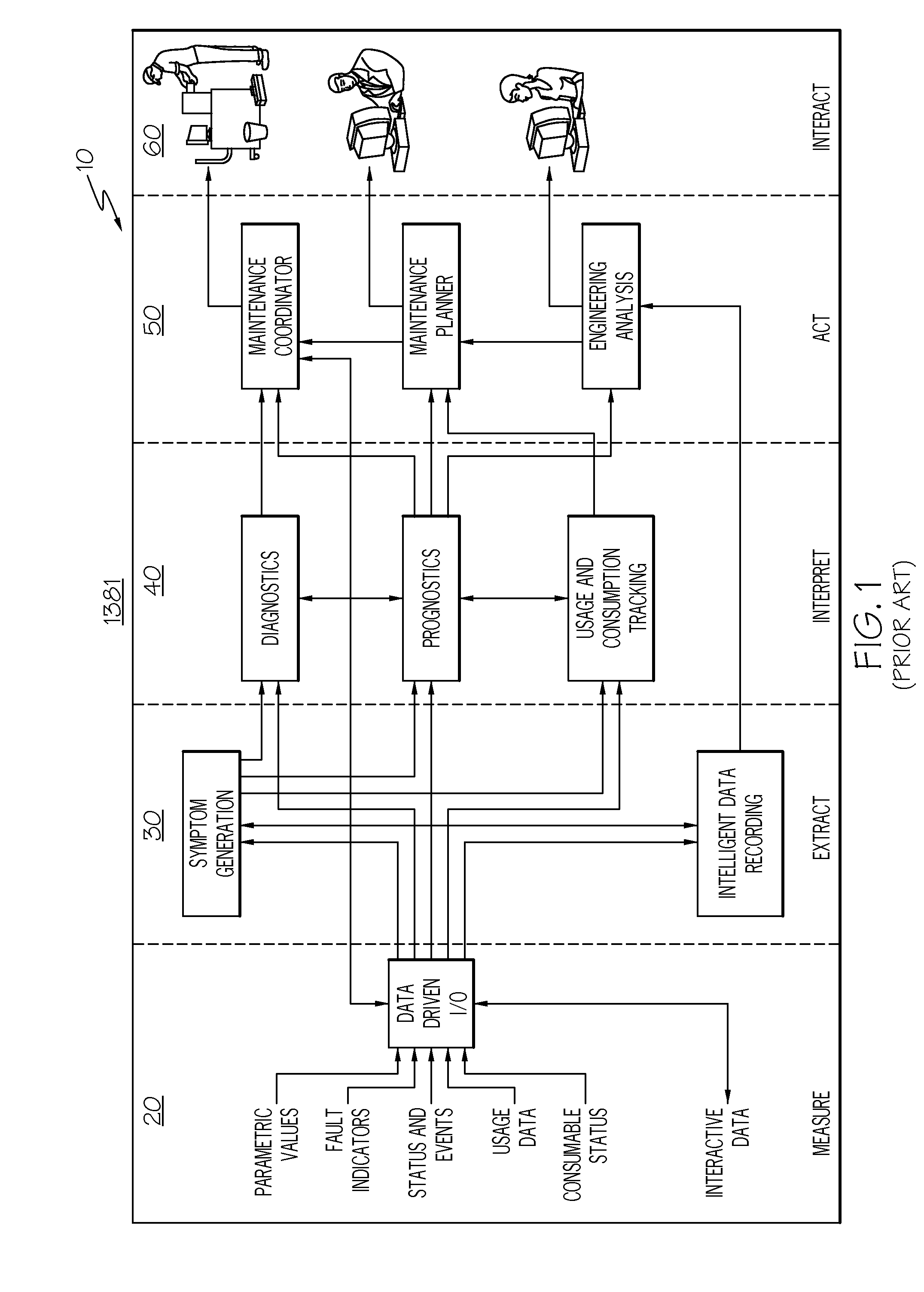
However, conventional CBM systems are generally rigidly configured requiring the user to live with cumbersome performance or pay significant modification costs.
Although processes required to implement a CBM system are becoming more widely known, the level of complexity of a CBM system remains high and the cost of developing these solutions is commensurately high.
Attempts to produce an inexpensive common CBM solution that is independent from the design of the complex system that is it is to monitor have been less than satisfying.

Method used


Image

  • Methods and systems for distributed diagnostic reasoning
  • Methods and systems for distributed diagnostic reasoning
  • Methods and systems for distributed diagnostic reasoning

Examples


Embodiment Construction

[0024]The following detailed description is merely exemplary in nature and is not intended to limit the invention or the application and uses of the invention. As used herein, the word “exemplary” means “serving as an example, instance, or illustration.” Thus, any embodiment described herein as “exemplary” is not necessarily to be construed as preferred or advantageous over other embodiments. All of the embodiments described herein are exemplary embodiments provided to enable persons skilled in the art to make or use the invention and not to limit the scope of the invention which is defined by the claims. Furthermore, there is no intention to be bound by any expressed or implied theory presented in the preceding technical field, background, brief summary, or the following detailed description.

[0025]Those of skill in the art will appreciate that the various illustrative logical blocks, modules, circuits, and algorithm steps described in connection with the embodiments disclosed herei...


PUM


Abstract

A method for distributed diagnostic reasoning is provided. The method includes establishing a computing node monitoring the operation of a component of a complex system and populating at least one of a processor and the memory of the computing node with one or more standardized executable application modules (SEAMs) and a workflow service. The method further includes creating a configuration file in combination with several SEAMS to create a distributed diagnostic reasoner (DDR) associated with the component. The method also comprises installing the configuration file in the computing node for execution by the processor; and initializing the one or more SEAMS, the configuration file and the workflow service, wherein the workflow service facilitates data flow between the one or more SEAMS and the static data associated with a fault condition resident in the configuration file.

Description

TECHNICAL FIELD[0001]The present invention generally relates to fault model architectures for condition based health maintenance systems monitoring a complex system, and more particularly relates to a diagnostic reasoner architecture that may be flexibly dissociated into a plurality of distributed diagnostic reasoners, where configuration data for each distributed diagnostic reasoner allows the distributed diagnostic reasoner to detect and analyze faults at the lowest practicable level in the complex system.BACKGROUND[0002]Increases in vehicle complexity and the accompanying increase in maintenance costs have led to industry wide investments into the area of condition based health management (CBM). These efforts have led to the development of industry or equipment specific process solutions. However, conventional CBM systems are generally rigidly configured requiring the user to live with cumbersome performance or pay significant modification costs.[0003]FIG. 1 is a simplified block...

Claims


Application Information

Patent Timeline
Patent Type & Authority Patents(United States)
IPC IPC(8): G06F11/00
CPCG05B23/0213
Inventor BELL, DOUGLAS ALLENFELKE, TIM
Owner HONEYWELL INT INC
Learn More