
Systems for providing zero latency, non-modulo looping and branching of test pattern data for automatic test equipment

a technology of automatic test equipment and test pattern data, applied in the field of integrated circuit testing, can solve the problems of increasing the size and complexity of integrated electronic systems, increasing the complexity of the methods and systems required to detect flaws within them, and increasing the complexity of the integrated electronic system. achieve the effect of efficient use of sram resources and high speed applications

Inactive Publication Date: 2005-01-04
VERIGY PTE
View PDF5 Cites 12 Cited by
  • Summary
  • Abstract
  • Description
  • Claims
  • Application Information

AI Technical Summary

Benefits of technology

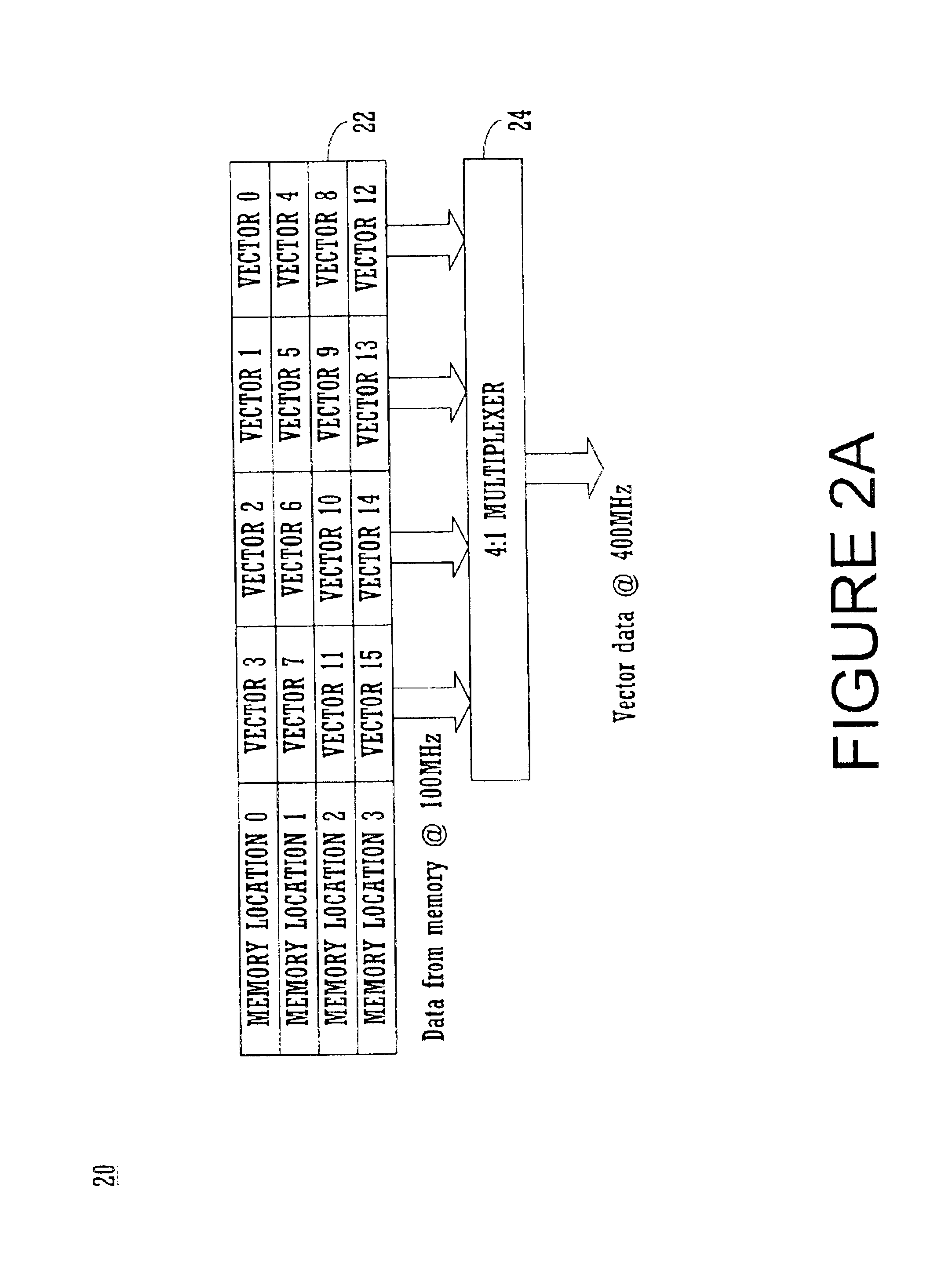
Accordingly, what is needed is an ATE system that solves the above recited problems. More specifically, what is needed is an ATE system that allows high speed application of test patterns while allowing nested looping without restrictions to loop size or modularity, e.g., that does not have modulo loop constraints. What is further needed is an ATE system that can loop and / or branch from any vector in a multiple vector accessed word to any vector in another multiple vector accessed word without incurring any time displacement. What is also needed, is such an ATE system that supplies vector data at a high but constant data rate and that efficiently uses SRAM resources. What is also needed is an ATE system that can continue from any vector in a multiple vector accessed word to the first vector in another pattern stored in memory (at an arbitrary location) without incurring any time displacement. The embodiments of the present invention provide such advantages. These and other aspects of the present invention not recited above will become clear within the descriptions of the present invention presented below.
In another embodiment, one vector sequence may call another vector sequence and the vector data may include an “end of pattern” control code which indicates the end of the presently addressed pattern. Unlike other control codes, this code is detected at the output of memory A and prior to writing the word into memory B. Detection of this code causes the memory address control unit to suspend writing into memory B, re-access the location of the next pattern to be executed from memory A and commence loading the start of that pattern into memory E (a special FIFO memory). The “end of pattern” word also specifies the “last vector in pattern” value, e.g., (0−(nV−1)). When the last vector in the existing pattern is executed, multiplexer B commences reading the initial sequence of the next pattern from memory E via a multiplexer G. Multiplexer G is set to the proper selection code based on the value of the multiplexer C selection in use at the time of the last word execution and the “last vector in pattern” value. In this way, the memories and the multiplexers dynamically select the correct vector from multi-vector words to facilitate contiguous data flow with no interruptions or restrictions on vector placement.

Problems solved by technology

Computer systems and electronic devices are continually growing in capability and complexity.
The size and complexity of integrated electronic systems are likewise increasing, making it critical that the component parts of these systems operate without fault.
However, as integrated circuit chips become more powerful, the methods and systems required to detect flaws within them become increasingly sophisticated and expensive.
Integrated circuit designs have become more complex in part because they are made more dense.
As a result, they have become progressively harder to test in order to ensure correct and complete functionality.
As such, the “place and route” tolerances for the integrated circuit are reduced, and the potential for introducing fabrication errors and introducing structural faults in the circuit increases.
Hence, the testing cost can be very significant for the latest and largest high density integrated circuits (ICs).
If the IC's output data is different from the provided expect data, then the IC fails the test and is classified as defective.
Typically, the more pins available on a tester, the more expensive the tester equipment.
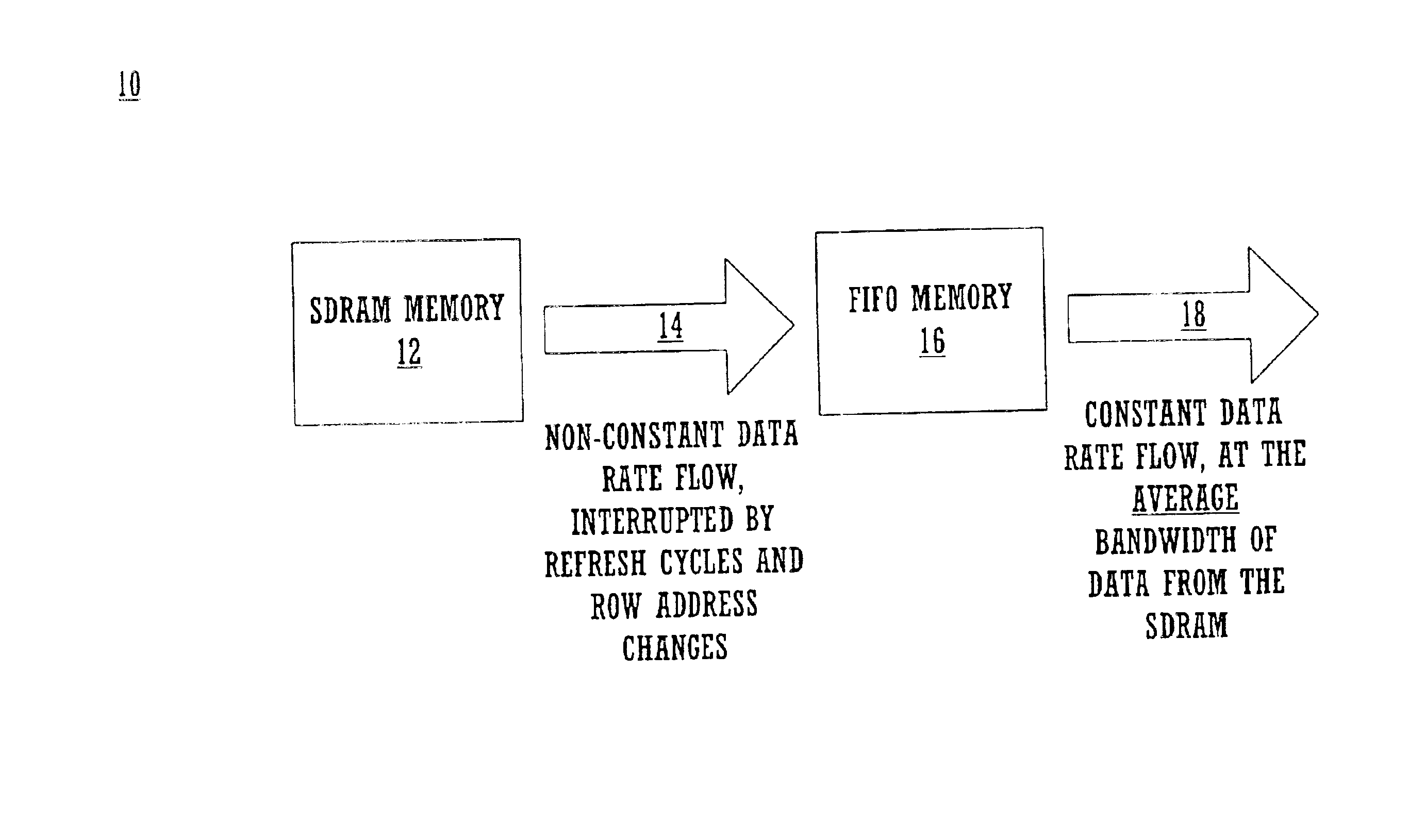
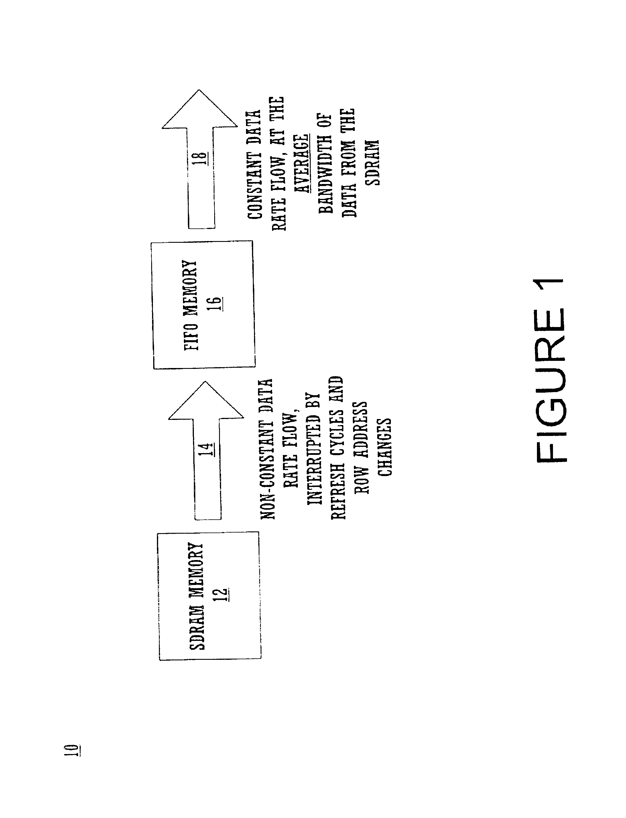
While SDRAMs have an acceptable high average bandwidth, they require periodic interruptions to the data flow for internal data refreshing and for row address changes.
This secondary memory 64 is much smaller and more expensive than the main SDRAM memory.
The first is that the amount of memory allocated for subroutines is limited by the size of the higher speed, but smaller sized SRAM, constraining both the number of available subroutines and the maximum size of the subroutines.
The SRAM is limited to a small size namely because: (1) it is very expensive; and (2) it is very technically difficult and complex to fabricate large SRAMs.
If the secondary memory also utilizes multiple vectors per memory access, that would impose a limitation that each subroutine would have to contain an even modulo number of vectors.
If incorrectly predicted, the speculative information would have to be cleared out, thereby breaking the continuous data flow.
However, this is often an undesirable solution.

Method used


Image

  • Systems for providing zero latency, non-modulo looping and branching of test pattern data for automatic test equipment
  • Systems for providing zero latency, non-modulo looping and branching of test pattern data for automatic test equipment
  • Systems for providing zero latency, non-modulo looping and branching of test pattern data for automatic test equipment

Examples


example operation

Upon the occurrence of a control word containing a “loop end” code, which also contains a “vector end vector” value (1−nV) and a “loop index” value, a loop may or may not be executed depending upon the state of a specified condition. The condition which could be the status of an externally generated event, or reaching a terminal count of a “loop counter” which was originally loaded on the first occurrence of the “loop begin” control word and subsequently decremented after each iteration of the loop.

If the specified condition is false, then the loop is not executed. If the condition is true, however, then the following events occur to execute the loop. FIG. 12A and FIG. 12B illustrate diagrams of the operation of the SRAM memory B 210b, the SRAM memory D 220b, the multiplexer B 430, the multiplexer C 420, the multiplexer D 415 and the multiplexer E 425 of circuit 200b of FIG. 8.

The multiplexer state machine 260b generates the correct selection codes for multiplexer B 430 and multiple...


PUM


Abstract

An SRAM efficient ATE system that performs high speed nested loops without constraints on loop size or modularity and that loops and / or branches from any vector in a multiple vector accessed word to any vector in another multiple vector accessed word without incurring any time displacement. In one embodiment, the maximum required vector rate is less than or equal the average sustained data rate of the SDRAM and is less than or equal to the maximum access rate of the dual port SRAM's memory B. The output of the SDRAM's memory A consists of one control word and one vector (nV=1). The I / O port widths of the SRAM's memory B are the same. In another embodiment, the maximum required vector rate is greater than the average sustained data rate of the SDRAM's memory A, but is equal to or less than the maximum access rate of the SRAM's memory B. The output of the SDRAM's memory A consists of multiple control words and vectors. The input port of the SRAM's memory B is some multiple of the output port width. In another embodiment, the maximum required vector rate is greater than both the average sustained data rate of the SDRAM's memory A and the maximum access rate of the SRAM's memory B. The output of the SDRAM's memory A consists of one or more control words (nW) and nW×nV number of vectors. The input port of the SRAM's memory B is nW times the width of the output port. The output port of Memory B contains 2 or more vectors per word.

Description

FIELD OF THE INVENTIONThe field of the present invention pertains to the testing of integrated circuits using automated testing equipment (ATE). More specifically, the invention pertains to circuits that enhance the functionality of test data pattern designs used in ATE and provides the capability to perform variable modulo looping of vector data sequences out of memory where the vector data rate is higher than the data rate of the memory being used.BACKGROUND OF THE INVENTIONComputer systems and electronic devices are continually growing in capability and complexity. The size and complexity of integrated electronic systems are likewise increasing, making it critical that the component parts of these systems operate without fault. This requires that each component, or integrated circuitchip,” be rigorously tested before it is sold. However, as integrated circuit chips become more powerful, the methods and systems required to detect flaws within them become increasingly sophisticat...

Claims


Application Information

Patent Timeline
Patent Type & Authority Patents(United States)
IPC IPC(8): G01R31/28G01R31/3181G01R31/3183G11C29/56G11C29/10G11C29/04
CPCG01R31/3181G01R31/3183G11C29/56004G11C29/56G11C29/10
Inventor BURLISON, PHILIP D.
Owner VERIGY PTE
Learn More