

Aircraft air-conditioning apparatus with water separators
a technology of air-conditioning apparatus and water separator, which is applied in the direction of lighting and heating apparatus, steam/vapor condensers, applications, etc., can solve the problems of increasing fuel consumption, requiring a comparatively large heat exchanger capacity, and affecting the air quality of the air-conditioning apparatus
- Summary
- Abstract
- Description
- Claims
- Application Information
AI Technical Summary
Benefits of technology
Problems solved by technology
Method used
Image

Examples
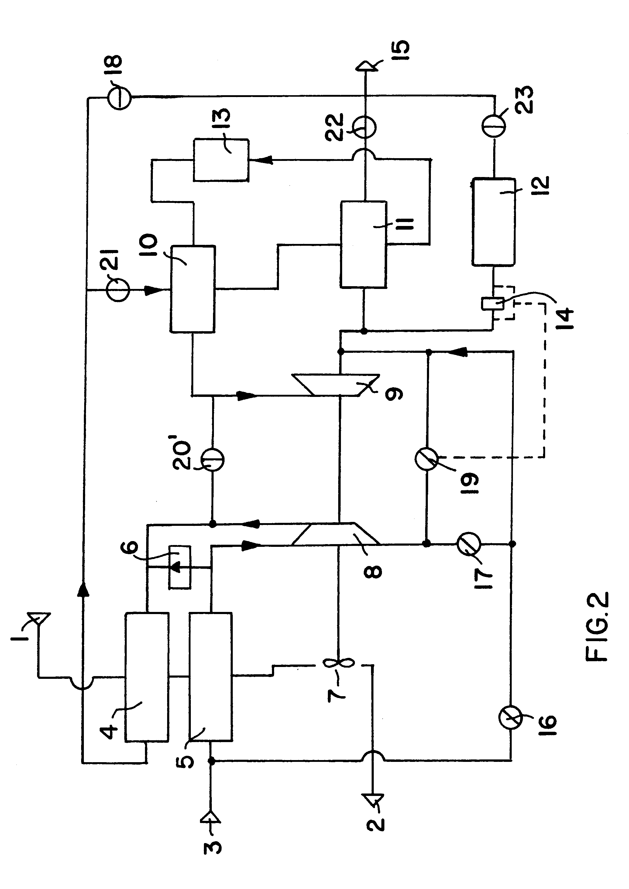
second embodiment
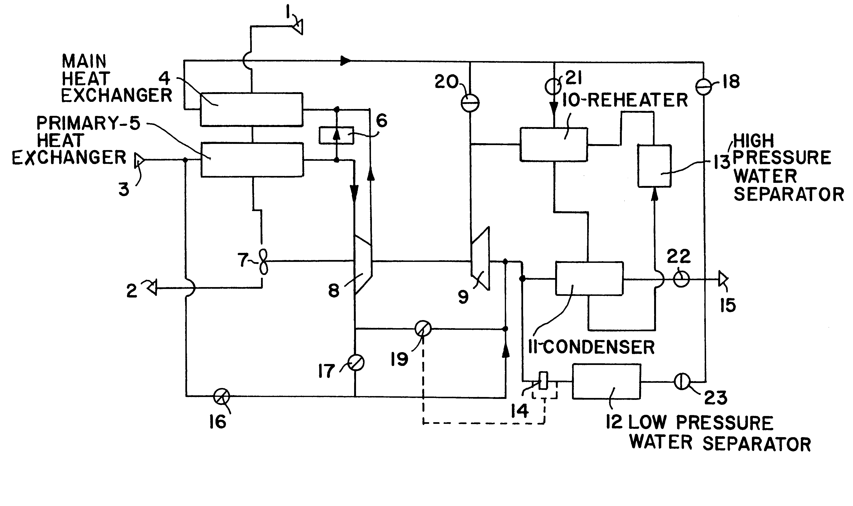
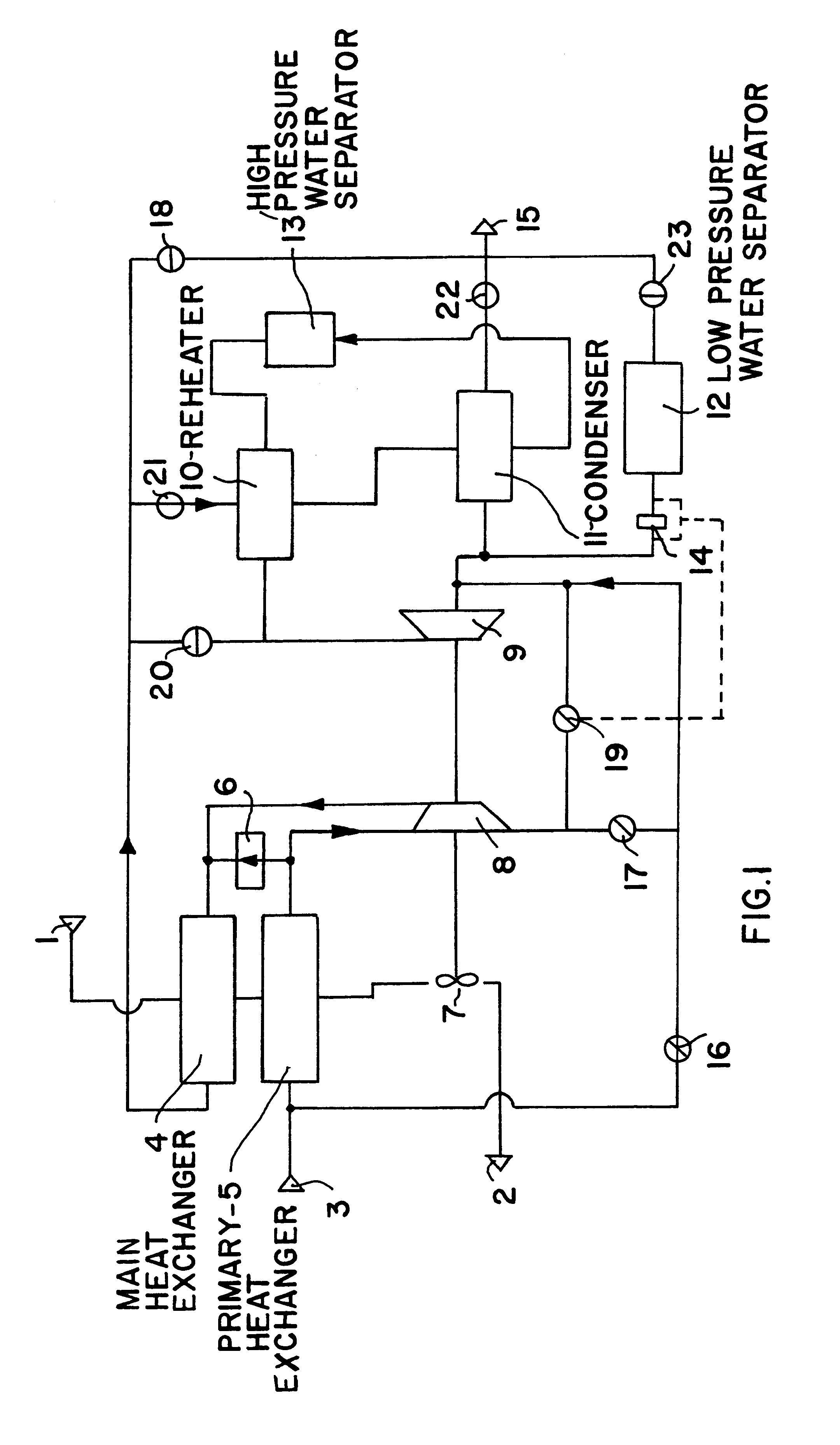
FIG. 2 shows an air-conditioning system according to the invention. The air-conditioning system according to FIG. 2 is otherwise identical to the above described system according to FIG. 1, except that the connection of the shut-off valve 20 of FIG. 1 has been changed to provide a shut-off valve 20' according to FIG. 2. Basically, one side of the shut-off valve 20' remains connected between the reheater 10 and the inlet of the expansion turbine 9, just as the valve 20 of FIG. 1. However, the other side of the valve 20' is connected to the air line that connects from the outlet of the compressor 8 to the main heat exchanger 4, rather than being connected to the air line downstream of the main heat exchanger 4 as is the valve 20 of FIG. 1. In other words, the valve 20' is connected between the outlet of the compressor 8 and the inlet of the turbine 9. Thus, while the operation of the system according to FIG. 2 otherwise remains the same as that according to FIG. 1, a pressure drop acr...
third embodiment
FIG. 3 schematically shows the inventive system, which is essentially identical to the embodiment of FIG. 1, except that it omits the bypass valve 17 and the turbine circumventing valve 19, and instead uses a combined valve 24, of which the operation is controlled by a signal converter 25 which is connected to the anti-icing grill 14. Particularly, the signal converter 25 detects the pressure difference arising across the anti-icing grill 14, and responsively actuates and controls the combined valve 24 in an electrical or pneumatic manner, for example. Thereby, it is possible to generate the signal resulting from and responsive to the pressure difference across the anti-icing grill 14 either electrically or pneumatically. The combined valve 24 is operated in an automatic or self-regulating manner to control the operation of the expansion turbine 9 and the mutually connected compressor 8, responsive to the degree of icing that occurs on the anti-icing grill 14. It should further be n...
PUM
 Abstract
Description
Claims
Application Information