Anchor system of a concrete wall formwork

a technology of anchor system and concrete wall, which is applied in the direction of walls, forms/shuttering/falseworks, and the like, can solve the problem that the anchor bar itself does not fit closely with the inner sealing ring, and achieve the effect of convenient removal of the anchor bar, convenient thread opening, and convenient placement of the threaded nut thread

Active Publication Date: 2014-05-20
PERI GMBH
View PDF11 Cites 4 Cited by
  • Summary
  • Abstract
  • Description
  • Claims
  • Application Information

AI Technical Summary

Benefits of technology

[0020]The anchor bar preferably has a rounded anchor bar tip, which makes it easier to find the thread opening on the free end of the guiding device. The anchor bar advantageously has a first thread in the end region of the anchor bar facing away from the anchor bar tip and a second thread in the end region of the anchor bar near to the anchor bar tip. In the intermediate region, the anchor bar advantageously has a smooth surface, which makes it more difficult for the concrete to become attached.
[0021]The anchor rod very advantageously conically tapers between the first and the second thread, which facilitates removal of the anchor bar after a cast concrete wall has set. The thread shape of the first thread can differ from the thread shape of the second thread so that the thread near to the anchor point can be constituted very coarsely, which makes it easier to locate the threaded nut thread of the threaded nut element. The inventive anchor bar has a stop in the region of the point, which, when threaded into the guiding device, fits closely in the free end of the guiding device. Prescribed wall thicknesses are easier to set and imprecise thicknesses of the wall that is to be cast in concrete are avoided.
[0022]The free end of the guiding device of the locking device located at the formwork element side is very advantageously aligned with the outside edge of the inner sealing ring located at the formwork element side or projects beyond the outside edge on the formwork element side. In this case, the outside edge of the inner sealing ring of the sealing element located at the formwork element side is essentially aligned with the front side of the formwork facing of the second formwork element. In this way, the edges of the anchor penetration hole are protected and any asymmetrical forces that are exerted on the inner sealing ring are optimally distributed across the width of the inner sealing ring. Here, only the guiding device fits closely in the inner sealing ring.

Problems solved by technology

The anchor bar itself does not fit closely against the inner sealing ring.

Method used


Image

  • Anchor system of a concrete wall formwork
  • Anchor system of a concrete wall formwork
  • Anchor system of a concrete wall formwork

Examples


Embodiment Construction

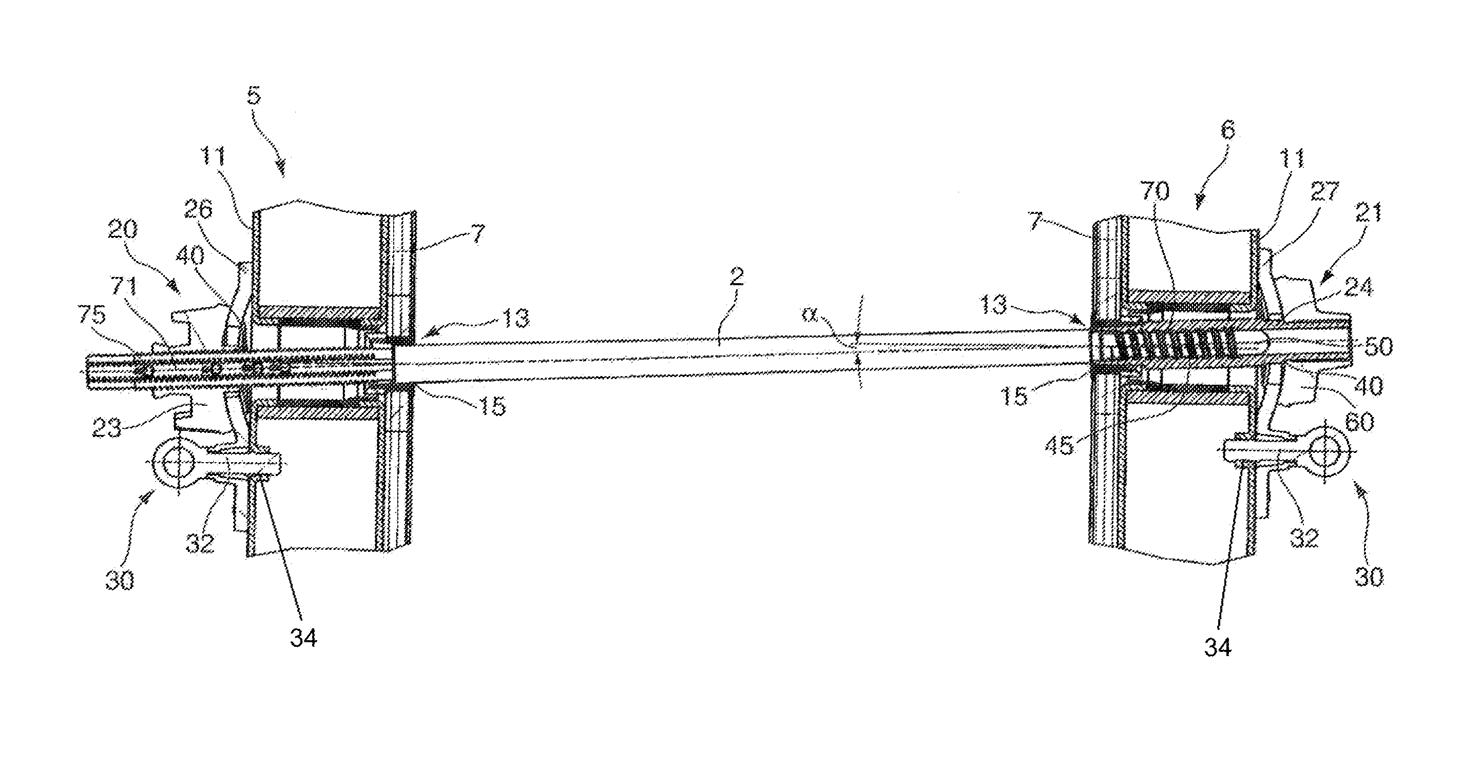
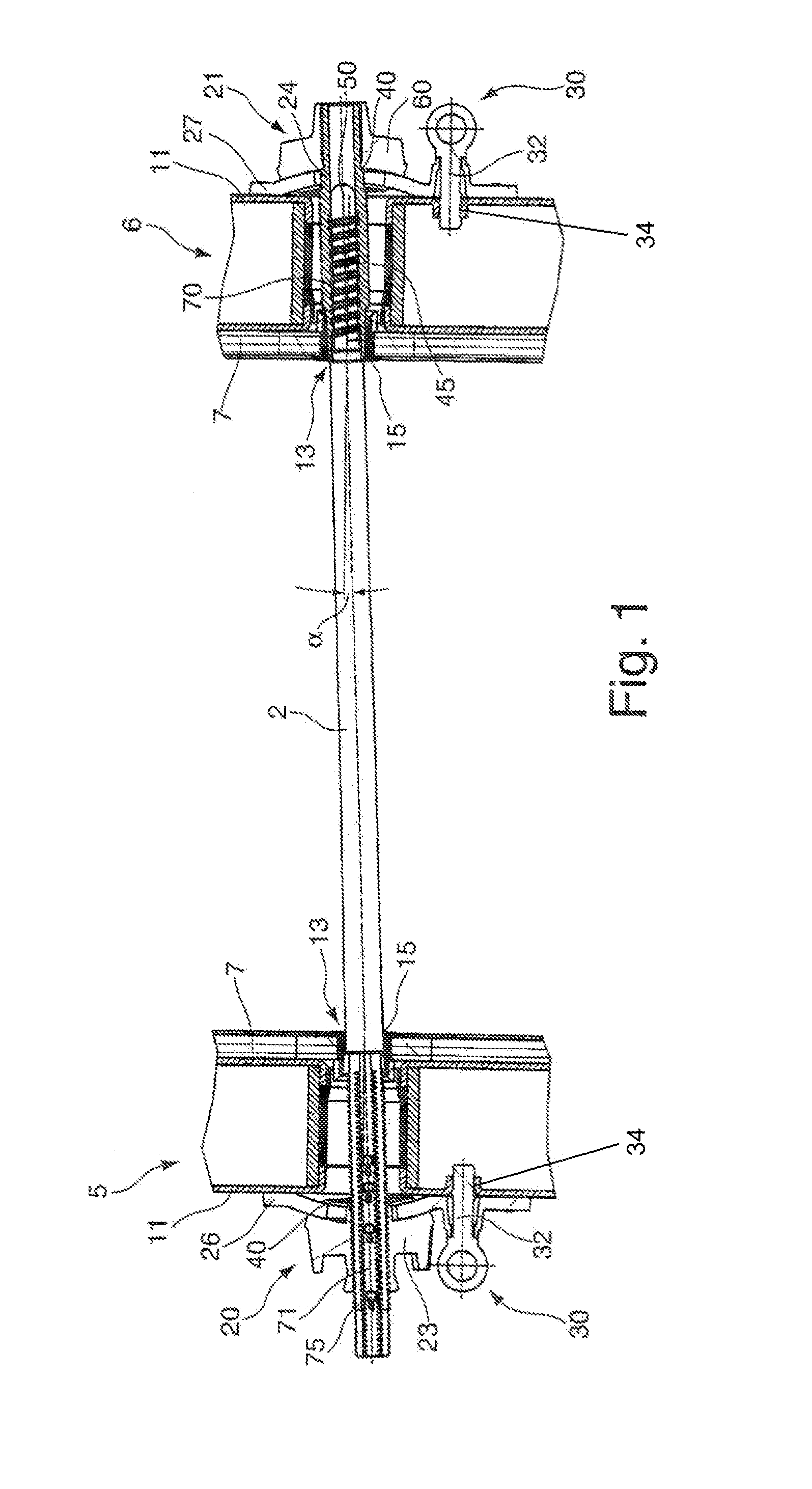
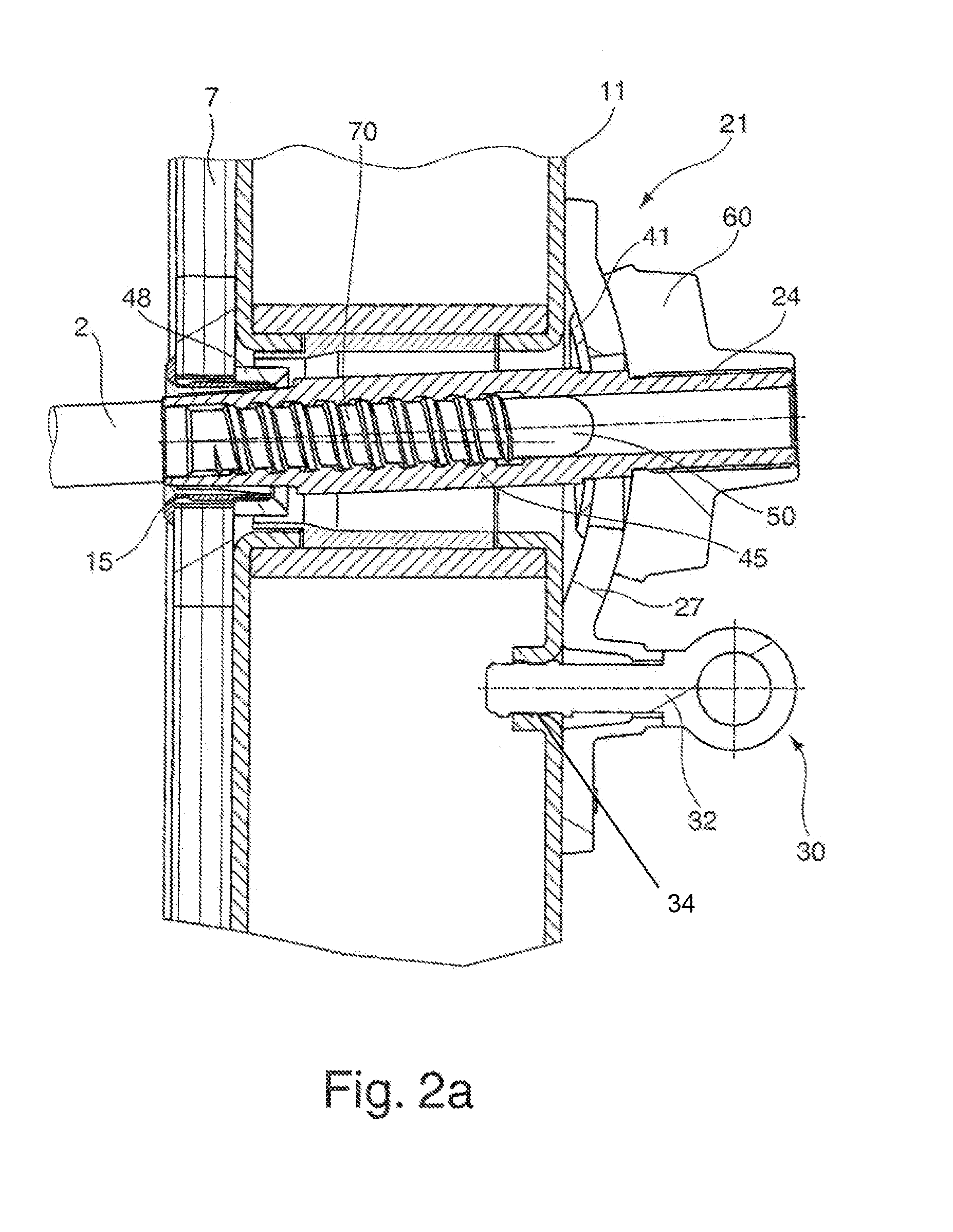
[0029]The figures of the drawings show the inventive object highly schematically and are not scale drawings. The individual parts of the inventive object are shown in such a way that their structure is clearly visible.

[0030]FIGS. 2a, 2b and 3 each show detail views of the inventive concrete wall formwork shown in FIG. 1, wherein each figure shows a cross-section at the level of the longitudinal axis of an anchor bar of the inventive anchor system, which connects a first and a second formwork element 5,6 of the concrete wall formwork. The formwork elements 5,6 each have a formwork facing 7 and longitudinal beams. Any tie beams that may exist are not shown due to the detail selected. The formwork facing 7 is usually mounted on longitudinal beams and tie beams, in particular, riveted on. The anchor bar 2 is aligned obliquely at an angle α with respect to the surfaces of the formwork facings 7.

[0031]In each case, the sectional representation in FIG. 1 extends through a longitudinal beam...


PUM


Abstract

A locking device 21 for an anchor bar 2 of an anchor system of a concrete wall formwork has an annular sealing element 15 for sealing off an anchor penetration hole 13 in the formwork facing 7 and a threaded nut element 24 for threading the anchor bar 2 into a threaded nut thread of the threaded nut element. A tubular guiding device 45 is flush with the threaded nut thread of the threaded nut element 24 on the end of the threaded nut element 24 to be located at the concrete formwork side. The sealing element 15 has an elastic rubber inner sealing ring 46 and the free end 51 of the guiding device 45 to be located at the formwork element side is sealingly inserted with the inner sealing ring 46 into the sealing element 15.

Description

[0001]This application is the national stage of PCT / EP2011 / 051419 filed on Feb. 1, 2011 and also claims Paris Convention priority of DE 10 2010 002 108.3 filed on Feb. 18, 2010.BACKGROUND OF THE INVENTION[0002]The invention relates to an anchor system of a concrete wall formwork with at least one locking device for an anchor bar of the anchor system, wherein the locking device has a threaded nut element for threading the anchor bar through a threaded nut thread of the threaded nut element.[0003]Such anchor systems are used in formwork for steel-reinforced concrete structures. Concrete formwork elements, or formwork elements for short, of concrete wall formworks are made up of a formwork facing and supporting elements, for example, longitudinal girders and tie beams. The two sides of a wall are each formed from one concrete formwork element, that is, a half-formwork, which are held together by anchor bars. The anchor bars are inserted through holes in the formwork facing and fixed at...

Claims


Application Information

Patent Timeline
Patent Type & Authority Patents(United States)
IPC IPC(8): E04G17/065
CPCE04G17/065E04G17/0657E04G17/0652E04G17/06
Inventor BRAUN, HANSRENZ, BERND
Owner PERI GMBH
Why Eureka
Try Eureka