Device for causing turbulent flow in a tank assembly

a technology of turbulent flow and tank assembly, which is applied in the direction of mechanical equipment, branching pipes, transportation and packaging, etc., can solve the problems of increasing the cost of a water system, degrading the tank, and the likelihood of problems stemming from air and water interaction is grea

Active Publication Date: 2014-06-03
AMTROL LICENSING INC
View PDF12 Cites 9 Cited by
  • Summary
  • Abstract
  • Description
  • Claims
  • Application Information

AI Technical Summary

Problems solved by technology

In any closed system containing air and water that undergoes natural or artificial temperature changes, the likelihood of problems stemming from interaction of air and water is great.
Pressure pumps and surge chambers increase the cost of a water system.
A disadvantage associated with conventional tank assemblies, such as the one disclosed in Lane, is that sediment builds up in the tank over time and ultimately degrades the tank.
An additional problem encountered in some conventional tank assemblies is that pockets of stagnant water develop within the fluid cell, resulting in the water becoming stale.

Method used


Image

  • Device for causing turbulent flow in a tank assembly
  • Device for causing turbulent flow in a tank assembly
  • Device for causing turbulent flow in a tank assembly

Examples


Embodiment Construction

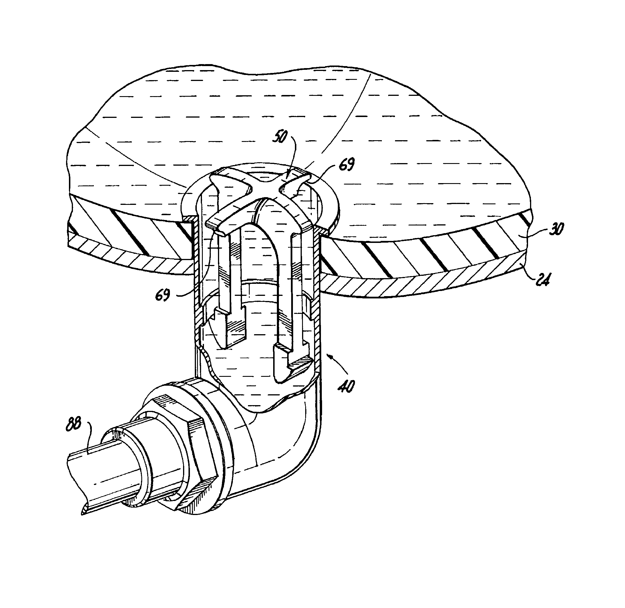
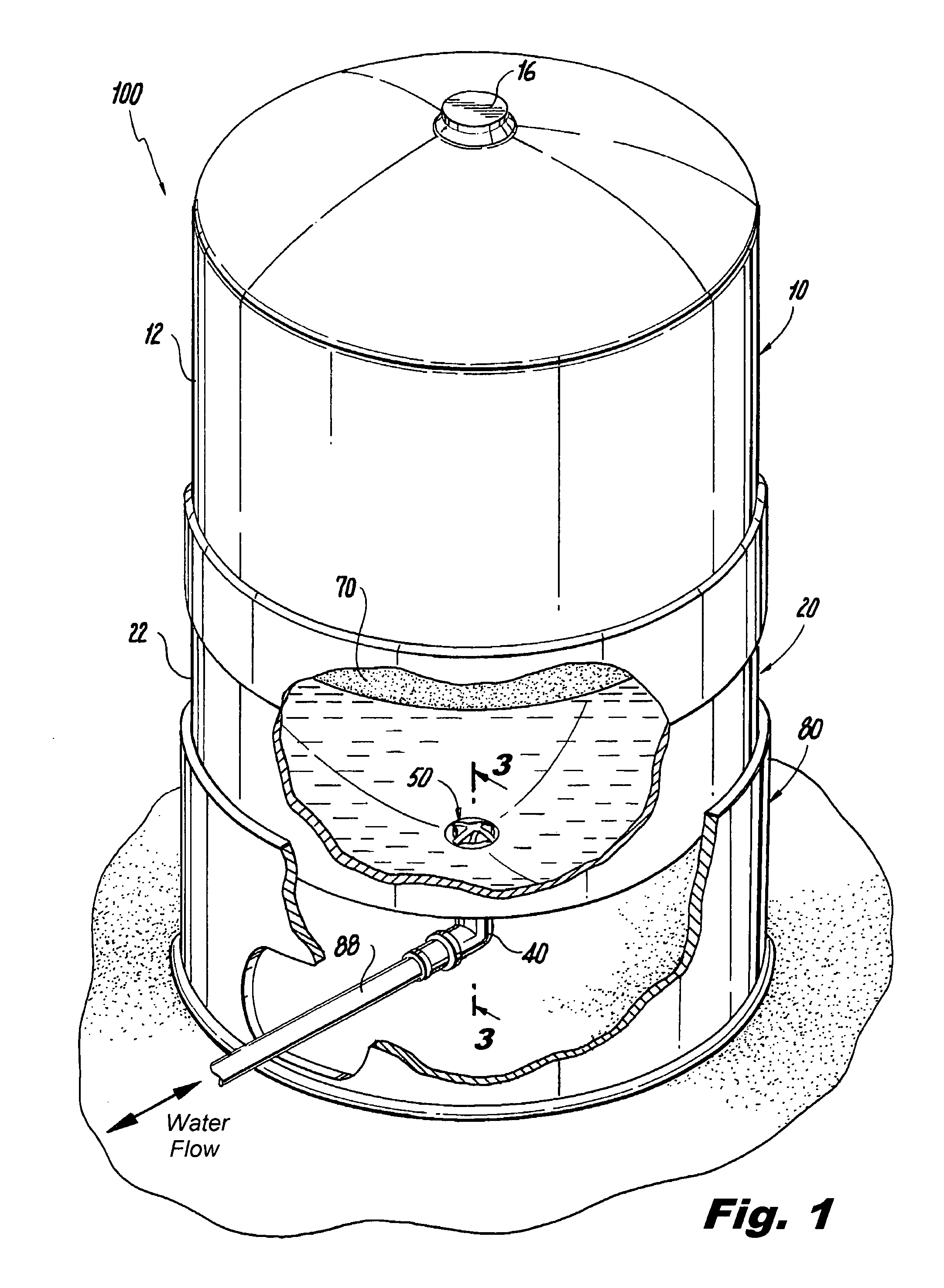
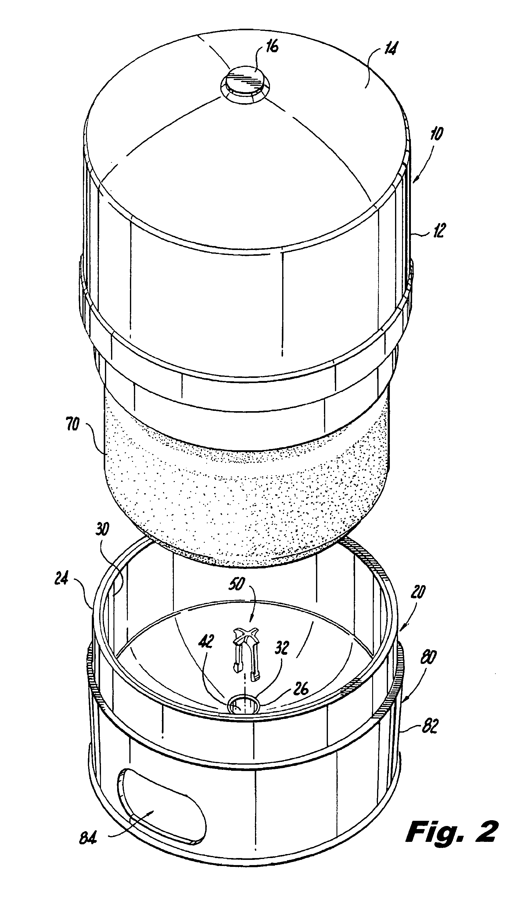
[0045]Disclosed herein are detailed descriptions of specific embodiments of the devices, systems and methods for causing turbulent flow in a tank assembly, such as a well tank. It will be understood that the disclosed embodiments are merely examples of the way in which certain aspects of the invention can be implemented and do not represent an exhaustive list of all of the ways the invention may be embodied. Indeed, it will be understood that the systems, devices, and methods described herein may be embodied in various and alternative forms. The figures are not necessarily to scale and some features may be exaggerated or minimized to show details of particular components. Well-known components, materials or methods are not necessarily described in great detail in order to avoid obscuring the present disclosure. Any specific structural and functional details disclosed herein are not to be interpreted as limiting, but merely as a basis for the claims and as a representative basis for ...


PUM


Abstract

Disclosed is a device for causing turbulent flow in a tank assembly that has an internal fluid cell and a fitting for allowing fluid to enter and exit the fluid cell from the exterior of the tank assembly. The device includes a main body portion and first and second retaining arms. The first and second retaining arms extend from the main body portion of the device and are adapted and configured for supporting the device substantially within the fitting of the tank assembly. A plurality of curved vane elements extend from the main body portion which cause turbulent flow in the fluid cell of the tank assembly by redirecting fluid entering the tank assembly axially through the fitting in a non-axial direction into the fluid cell.

Description

BACKGROUND OF THE INVENTION[0001]1. Field of the Invention[0002]The subject invention is directed to a device for causing turbulent flow in a tank assembly, and more particularly to, a device associated with a tank's fluid inlet which creates turbulent flow within the tank, a still more particularly to, a device for use with a tank assembly, such as a well tank, which includes a plurality of vane elements that alter the direction of fluid flow entering the tank so as to cause turbulent flow within the tank.[0003]2. Description of the Related Art[0004]Water systems that provide and distribute well water domestically in rural parts of the country typically include a pump to draw water from the well; pipes or other conduits through which water travels; and a tank for storing water, e.g., a well tank. Well tanks, e.g., expansion tanks, are structured and arranged to store water until demanded and to accommodate internal pressures of the system. To this end, well tanks typically provide ...

Claims


Application Information

Patent Timeline
Patent Type & Authority Patents(United States)
IPC IPC(8): F17D1/00
CPCE03B11/04E03B11/12Y10T137/85938Y10T137/86348Y02A20/00
Inventor VAN HAAREN, CHRISTOPHER A.CERPOVICZ, KENNETH
Owner AMTROL LICENSING INC
Why Eureka
Try Eureka