Variable speed pipeline pig with internal flow cavity

a variable speed, pipeline technology, applied in the field of pipeline pigs, can solve the problems of increasing the likelihood that the pipeline pig will become stuck in the pipeline, slowing the pipeline pig below a minimum, and building debris within the pipeline that can be problematic for the operation of the pipeline pig

Active Publication Date: 2017-11-07
SAUDI ARABIAN OIL CO
View PDF36 Cites 3 Cited by
  • Summary
  • Abstract
  • Description
  • Claims
  • Application Information

AI Technical Summary

Benefits of technology

The patent describes systems and methods for controlling a pipeline pig to clear blockages in a pipeline. The system includes a housing with a bypass channel and a relief channel. A bypass valve is positioned in the bypass channel to control fluid flow through the channel. The system also includes a closure member that can be moved between a restrictive and bypass configuration to control the speed and force of the pipeline pig. The system allows for the regulation of the flow of fluid through the pipeline pig and the force applied to clear blockages, making it easier to clear blockages and restore fluid flow through the pipeline.

Problems solved by technology

Buildup of debris within the pipeline can be problematic for the operation of the pipeline pig.
Debris ahead of the pig may slow the pipeline pig below a minimum speed required for carrying out the desired application, or in some instances, can completely prevent the pipeline pig from moving forward through the pipeline.
Also, flow channels for regulating a speed of the pipeline pig reduce the maximum fluid force that can be applied to the pipeline pig to drive it through the pipeline, and thus can increase the likelihood that the pipeline pig will become stuck in the pipeline when debris or other obstructions are encountered.
If the pipeline pig becomes stuck in the pipeline, flow of the pipeline fluid can be restricted or impeded.
This contingency plan is costly due to inhibited pipeline flow and downtime while the pipeline is cleared.

Method used


Image

  • Variable speed pipeline pig with internal flow cavity
  • Variable speed pipeline pig with internal flow cavity
  • Variable speed pipeline pig with internal flow cavity

Examples


Embodiment Construction

[0025]The present invention will now be described more fully hereinafter with reference to the accompanying drawings which illustrate embodiments of the invention. This invention may, however, be embodied in many different forms and should not be construed as limited to the illustrated embodiments set forth herein. Rather, these embodiments are provided so that this disclosure will be thorough and complete, and will fully convey the scope of the invention to those skilled in the art.

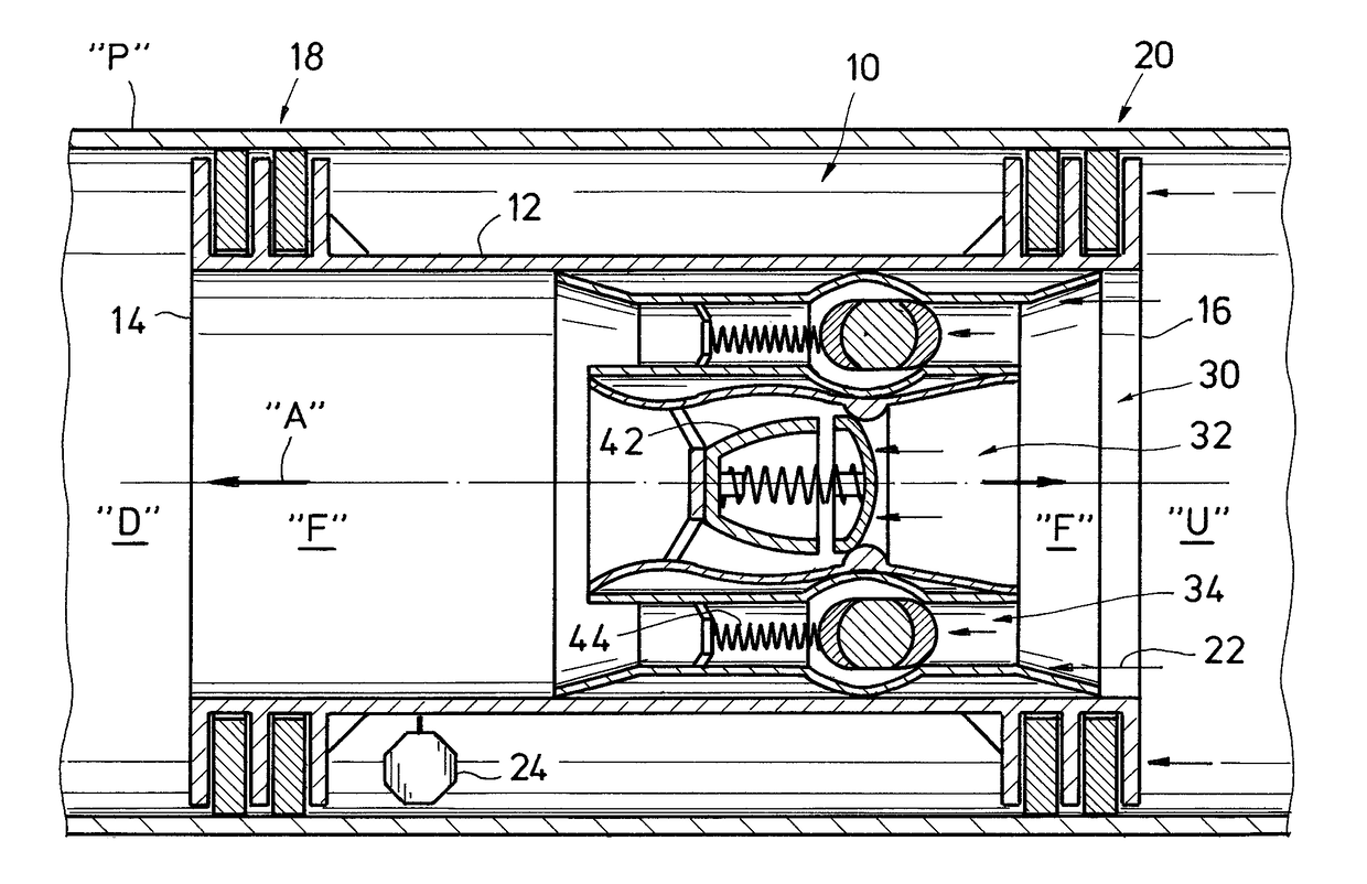
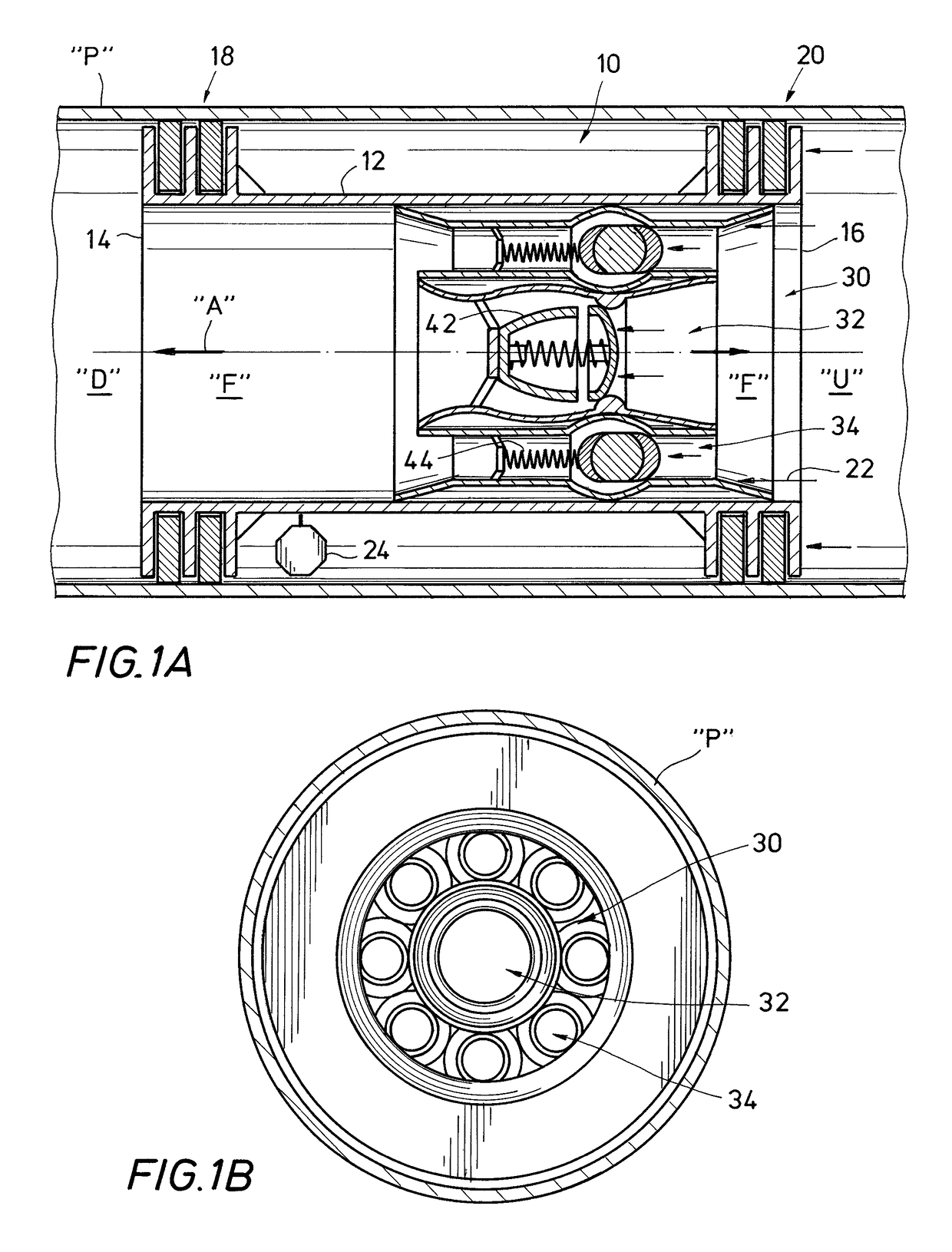
[0026]Referring to FIGS. 1A and 1B, pipeline pig 10 is constructed in accordance with an example embodiment of the present invention, and is disposed within an interior of pipeline “P.” Pipeline pig 10 includes housing 12, which defines a downstream or leading end 14, an upstream or trailing end 16 and longitudinal axis “A” extending therebetween. A pressure differential established in pipeline fluid “F” between leading end 14 and trailing end 16 propels pipeline pig 10 through the interior of pipeline “...


PUM


Abstract

A pipeline pig includes a plurality of relief channels and a bypass channel extending therethrough. To regulate a speed of the pipeline pig, relief valves within the relief channels open when a differential pressure between upstream and downstream ends of the pipeline pig reaches a pre-selected minimum relief pressure. If the differential pressure reaches a pre-selected maximum relief pressure, such as when the pipeline pig encounters an obstruction, the relief valves close to allow the differential pressure to further increase to clear the obstruction. If the further increase in differential pressure is insufficient to clear the obstruction and the differential pressure reaches a pre-selected minimum bypass pressure, a bypass valve opens to permit fluid flow through the bypass channel while the relief valves are closed. Flow through the bypass channel operates to reduce turbulence and permit production through the pipeline if the pipeline pig becomes stuck and obstructs the pipeline.

Description

BACKGROUND OF THE INVENTION[0001]1. Field of the Invention[0002]Embodiments of the present invention relate generally to a pipeline pig that is propelled by the pressure of a pipeline fluid flowing through a pipeline. In particular, embodiments of the invention relate to a pipeline pig with a plurality of distinct flow channels extending therethrough that selectively permit and prohibit flow of the pipeline fluid through the pipeline pig.[0003]2. Description of the Related Art[0004]An instrument for inspecting, cleaning, and maintaining a pipeline is often referred to as a pipeline pig. In some applications, the pipeline pig is propelled along an interior of the pipeline under the pressure of a pipeline fluid flowing through the pipeline. To facilitate advancement of the pipeline pig, one or more flexible guide disks or cups are often provided that extend outwardly from a longitudinal body of the pipeline pig. The flexible guide disks extend to an interior wall of the pipeline so as...

Claims


Application Information

Patent Timeline
Patent Type & Authority Patents(United States)
IPC IPC(8): F16L55/10F16L55/38B08B9/055F16L101/12F16L101/30
CPCF16L55/38B08B9/0551B08B9/0553F16L2101/30F16L2101/12
Inventor SOLIMAN, MOHAMED AHMED A.
Owner SAUDI ARABIAN OIL CO
Why Eureka
Try Eureka