Apparatus and method for flowing compressed fluids into and out of containment

a technology of apparatus and fluids, applied in the direction of liquid transferring devices, non-pressure vessels, packaging, etc., can solve the problems of insufficiently addressing the challenges of efficient loading, limited effective strength of materials used to fabricate these essentially rigid containers, and heat energy build-up within storage containers

Active Publication Date: 2008-09-04
WHITE CHARLES N +1
View PDF37 Cites 105 Cited by
  • Summary
  • Abstract
  • Description
  • Claims
  • Application Information

AI Technical Summary

Benefits of technology

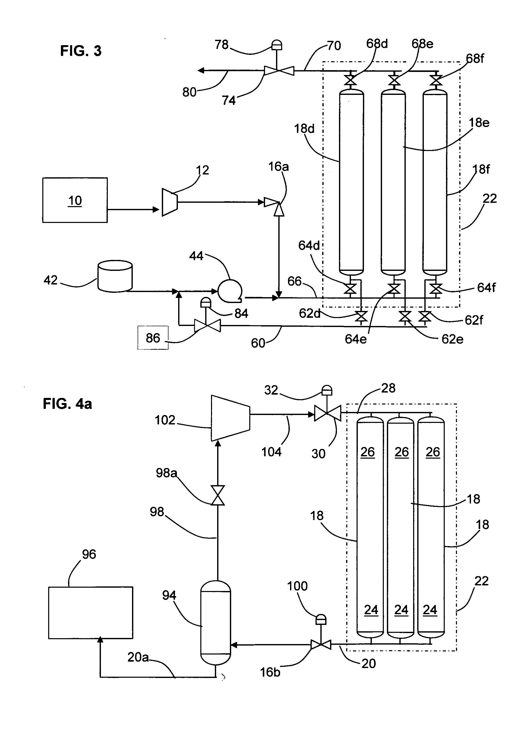
[0027]In one embodiment, a separator is provided in the flow path for separating the compressed fluid into a lower density stream and a higher density stream, and after the pressure in the containment system drops to the point such that the actual flow rate in the flow path is nearly at or below the desired flow rate, the lower density stream from the separator is injected into a compressor. The lower density str

Problems solved by technology

Compressed fluids have been typically contained in relatively (or very) long cylinders, bullet tanks, oblate spheroids or spheres that all feature at least one circular cross-section cut and have relatively high wall thickness to diameter ratios (t/D) to resist the pressure-induced hoop stresses because the materials used to fabricate these essentially rigid containers are of limited effective strength in the orientation of the critical stresses (whether metallic or fiber-based matrix shells or hybrid composites thereof).
Existing art does not adequately address the challenges of efficiently loading and discharging compressed fluids, particularly pressurized, refrigerated natural gas cargos, which would be useful for establishing commercially attractive storage and transport services.
If a displacement practice is not adopted for loading and unloading of pressurized gas cargos, expansion and recompression of gases within the containment can result in heat energy build up within storage containers, which impacts the efficiency undesirably.
The amount of residual gas remaining in storage after normal discharge operations is another issue that challenges existing compressed gas storage and transport concepts because this quantity of gas, frequently called heel, cannot be sold.
The cost and effectiveness of scavenging compression systems are impacted by the compression ratio needed to push gas into pressurized receiving infrastructures (e.g., a gas transmission pipeline) by raising the pressure of discharging gas from an inlet pressure that is dropping relative to the back pressure imposed by the receiving infrastructure.
In commercial scenarios, it is undesirable to warm a deeply chilled containment system up to ambient temperature and impractical to wait the many days needed to do so.
Liquid displacement makes it possible to remove all cargo gas from storage, but the liquid displacement system incurs high costs for acquiring at least one reservoir of the liquid, refrigeration and insulation to keep it at the proper temperature, and a pumping system to drive the liquid into the containment system against its internal pressure.
However, it is not practical to use for operating temperatures much below −30° C. because of increasing viscosity.
Further, costly r

Method used


Image

  • Apparatus and method for flowing compressed fluids into and out of containment
  • Apparatus and method for flowing compressed fluids into and out of containment
  • Apparatus and method for flowing compressed fluids into and out of containment

Examples


Embodiment Construction

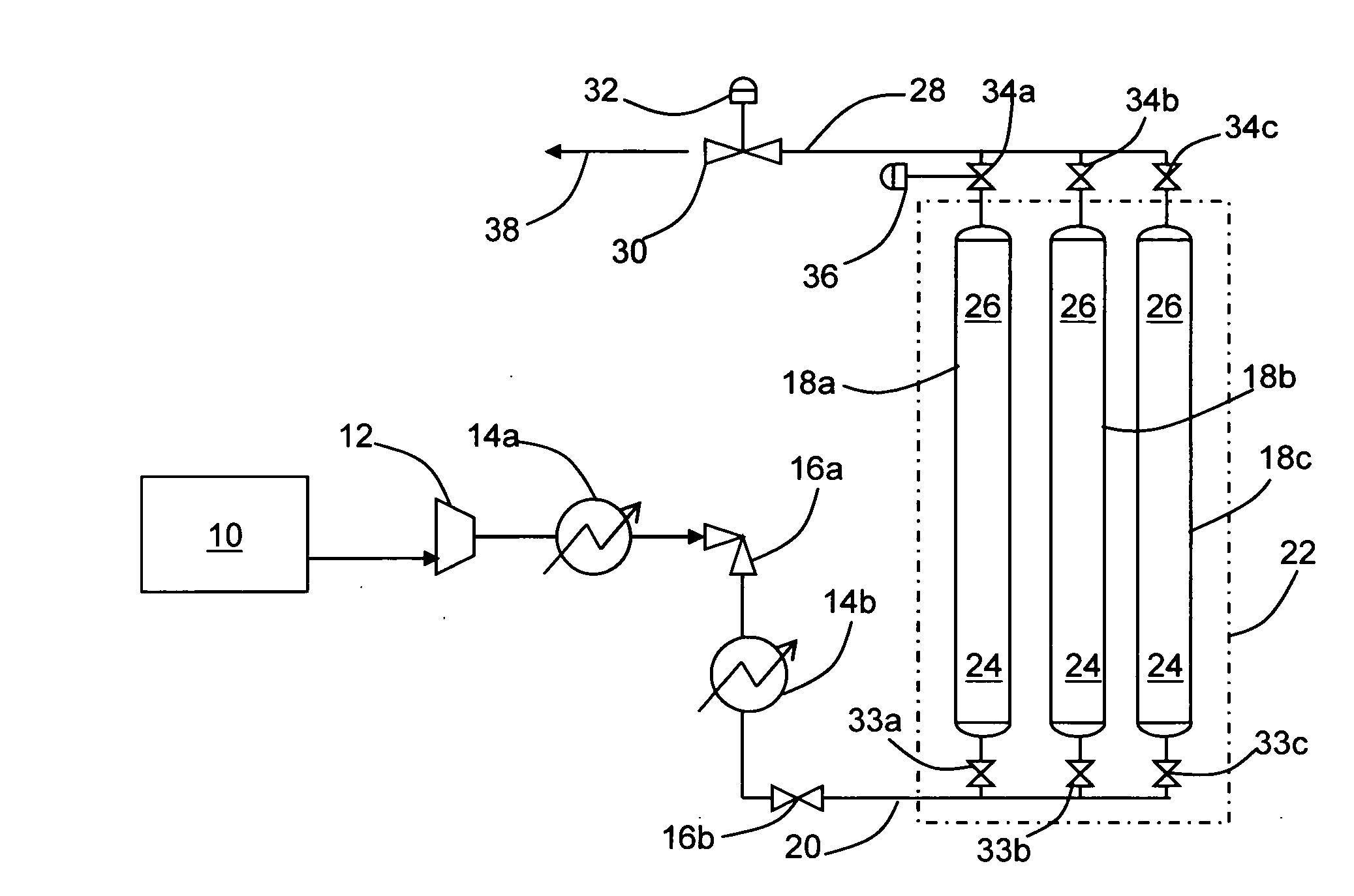
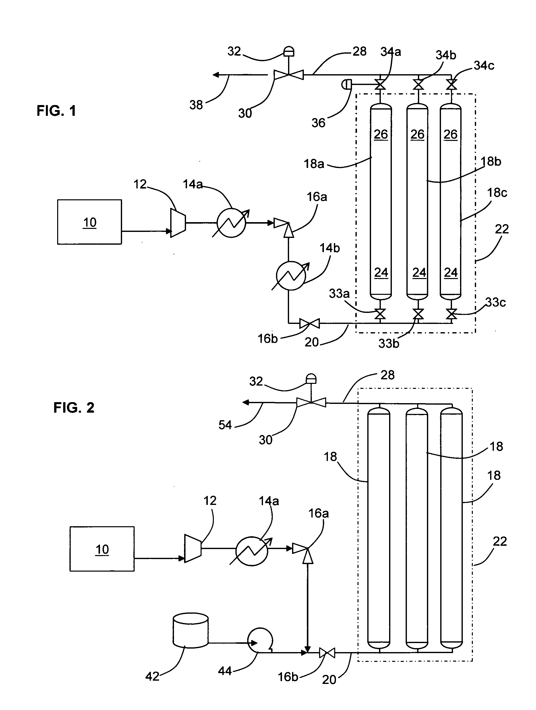
[0035]The present invention provides innovative means for loading a compressed fluid cargo into stationary or transportable cargo containers and for discharging the cargo from the containers. The compressed fluid cargo is typically refrigerated to a stable storage condition at a temperature substantially below 0° C. Since a transport system should address both loading and unloading efficiencies, this invention also addresses means for discharging or withdrawing cargo from the containment system used for storage and / or transportation such that the amount of residual fluid in the containment system (above any amount required as fuel for a return trip) at the end of the withdrawal process is minimized.

[0036]The containers described herein may be designed and used to efficiently hold a wide variety of fluids (e.g., gases and gas compositions) in dense pressurized states that may be gaseous, liquid, or mixed phase. The pressures at which natural gas and / or natural gas liquids and their a...


PUM

PropertyMeasurementUnit
Temperatureaaaaaaaaaa

Abstract

Methods for loading a compressed fluid, such as natural gas, into and discharging the compressed fluid out of containment are provided. The compressed fluid is injected into a bottom portion of a container system for storage and/or transport until a target pressure is reached after which gas is withdrawn from an upper portion of the container system at a rate to maintain the target pressure while the compressed fluid is injected in the bottom portion. The compressed fluid is cooled through an expansion valve and by refrigerated chillers or by injecting a cold liquid of the same chemical composition as the compressed fluid, such as liquid natural gas, into the compressed fluid prior to injection into the container system. Withdrawal or discharge from the container system to a receiving facility begins with blow down from the bottom portion of the container system without a displacement fluid and continues until pressure falls below an acceptable differential pressure. The discharge stream is passed through a separator and a light gas from the separator is pressurized and injected into an upper portion of the container system to drive the compressed fluid out the bottom. The light gas is pressurized using either a compressor or a heated tank system, where two vessels operate in parallel, trapping and heating the light gas and then discharging to the container system from one while filling the other and alternating the operation between the two.

Description

CROSS REFERENCE TO RELATED APPLICATION[0001]Priority is claimed to U.S. Provisional Patent Application Ser. Nos. 60 / 904,541 and 60 / 926,504, each of which was filed by the present inventor on Mar. 2, 2007, and Apr. 27, 2007, respectively, and each is incorporated by reference. A U.S. patent application filed by the present inventor on a date concurrent herewith, which claims priority to the same provisional patent applications, entitled “Storing, Transporting and Handling Compressed Fluids” is related hereto and incorporated by reference.BACKGROUND OF THE INVENTION[0002]1. Field of the Invention[0003]The present invention pertains to apparatus and methods for handling fluids, and more particularly to apparatus and methods for charging a compressed fluid into or discharging the compressed fluid out of containment, including into and out of a storage or transport container.[0004]2. Description of the Related Art[0005]Gases are stored and transported under pressure to reduce the volume ...

Claims


Application Information

Patent Timeline
IPC IPC(8): F17C5/02B63B25/14F17C5/00F17C5/04F17C5/06F17C7/00F17C7/02F17D1/00B67D5/00B67D99/00
CPCF17C2201/0104F17C2227/0339F17C2205/0176F17C2223/033F17C2227/0388F17C2227/0341F17C2227/0192F17C2205/0111F17C13/026F17C2205/0146F17C2227/0157F17C2201/054F17C2223/043F17C2270/01F17C2225/0123F17C2225/0153F17C2227/0372F17C2250/0631F17C2225/046F17C2227/043F17C2223/046F17C2225/0115F17C2225/033F17C2223/0123F17C2221/011F17C2270/0105F17C2221/012F17C2221/031F17C2223/0153F17C2201/032F17C7/00F17C13/025F17C2221/014Y10T29/49826F17C2221/033F17C5/02F17C7/02F17C5/06F17C2201/052F17C2265/022F17C2221/035Y02E60/321F17C2205/013F17C2223/0115F17C2225/035F17C2250/0626F17C2205/0142F17C2227/048F17C2227/0337F17C2270/0134Y02E60/32Y10T137/0324F17C13/04
Inventor WHITE, CHARLES N.
Owner WHITE CHARLES N
Why Eureka
Try Eureka